User manual 5-1
DSC/DSCT Series
5. DESCRIPTION OF THE SIGNALS ON THE CONNECTORS
5.1. CONNECTING CABLE TO RESOLVER (CONNECTOR J4)
DB9 FEMALE TYPE CONNECTOR TO BE CONNECTED TO RESOLVER AS SHOWN IN THE FOLLOWING FIGURE
J4
DB9 FEMALE TYPE CONNECTOR MOTOR
CONNECTOR
RESOLVER
TRANSF. RATIO
1: 0.5
1: 0.45
R1
R3
S1
REF
0REF
0COS
3
4
5
RESOLVER FEEDER OUTLET
(6,5 VOLT RMS - 7,8 KHz - MAX 20mA)
RESOLVER SIGNAL INPUT
RESOLVER SIGNAL INPUT
COS
0SIN
6
8
S3
S4
S2SIN
SP6
0SP6
7
1
2
MOTOR THERMAL SW ITCH
J2-10V
CABLE
CONNECTING
SWITCH
THERMAL
MOTOR
THEY MUST HAVE THE SAME FEATURES.
THE RESOLVER MUST BE OF THE SAME TYPE ALREADY USED, SEE TABLE, OR
RAP.TRAS. 0.5RESOLVER ARTUS ES. 26S19RX452b.F
CABLE : INTERCOND SPECIALFLEX H
fi
. 1
USED TAMAGAWA ES. TS2640N71E10
4x(2x0.25SK) COD. 2MB 24P 04R
RAP.TRAS. 0.5
PLUS EXTERNAL SHIELD.
THE SHIELD ON THE CONNECTOR SIDE J4 MUST BE CONNECTED TO
TERMINAL 1 OF CONNECTOR J2 AND FINALLY CONNECTED TO THE
THE CONNECTING CABLE MUST BE 4-BIGHTS PLAIED AND SHIELDED
ADJUSTING EARTH BAR AS SHOW IN PARAGRAPH 1.2.
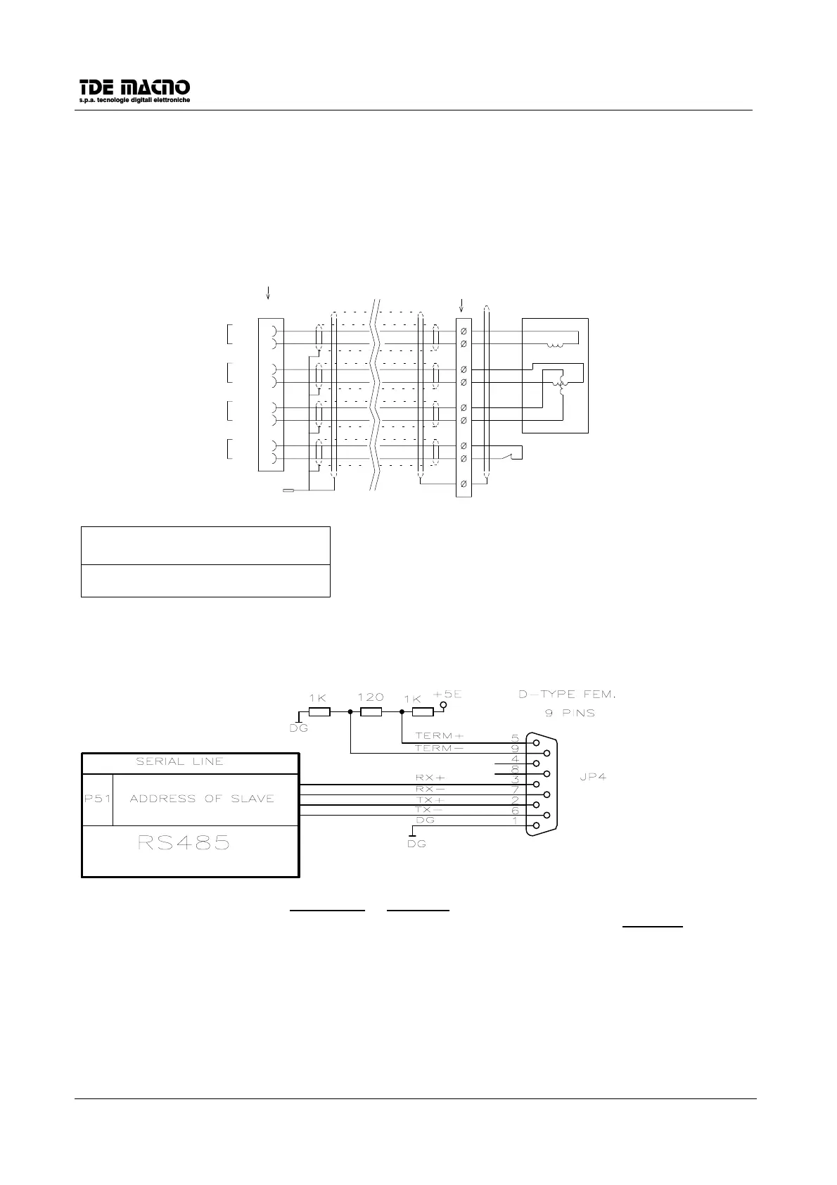
5.2. SERIAL LINE CONNECTOR (CONNECTOR J5)
The serial line communicates in half duplex on four wires: RX+ and RX- are receiving wires for the drive
while TX+ and TX- are transmitting wires. It can be done the connection with only two wires connecting
together RX+ and TX+, and RX- and TX- (each couple of wires must be twisted).
There is the possibility to ‘terminate’ the connection with 120Ω of impedance and polarizing the line
connecting the terminals 5 with 3 and 9 with 7.
It is available a simple PC supervisor software ( DOS or Windows 95) for the DSC/DSCT series drives.
 Loading...