User manual 14-2
DSC/DSCT Series
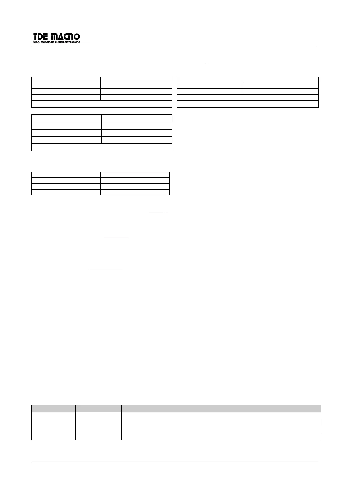
Examples of a DSC/DSCT SLAVE connected to a DSC/DSCT MASTER with frequency input as standard encoder.
From a DSCx MASTER we have considered the simulated encoder signals A,A,B,B
and we have connected them to a DSCx SLAVE
frequency input. By programming the parameter P61 it’s possible to select the sliding between two DSCx (P61=4096 => 100%).
MASTER SLAVE MASTER SLAVE
c11=4 (512) c11=4 (512) c11=4 (512) c11=4 (512)
P52=2500rpm P52=2500 rpm P52=2500rpm P52=2500 rpm
P61=4096 P61=2048
The SLAVE run at the same MASTER speed The SLAVE run at half of MASTER speed
MASTER SLAVE
To obtain good performances at low speed, it’s
c11=4 (512) c11=4 (512)
necessary to select a sufficient high encoder
P52=2500rpm P52=2500 rpm
resolution (C11 in DSCx MASTER).
P61=8192
The SLAVE run double of MASTER speed
Example
: With the drives set as in the following table, the desired speed of the slave is 1/4 of the master.
MASTER SLAVE
c11=7 (4096) c11=7 (4096)
P52=3000rpm c14=1 (A, A/,B,B/)
P54=2
Input frequency of the slave is :
HzFr
204800
2
2
60
3000
4096
==
the above formula for P61 is:
14
60
4096
61
c
Fr
N
RPMP
slave
⋅
⋅
⋅
⋅=
,
and with the real parameters yelds:
10241
0480060
40964096
75061
=⋅
⋅
⋅
⋅=
2
P
With 4096 enc. pulses/electrical rev. each motor shaft rev. corresponds to 4096 reference pulses (with 2 pole
resolver), and each reference pulse corresponds to 1/4096 rev. of the motor shaft.
14.1. END OF MOVEMENT LOGIC OUTPUT
The drive can output an "end of movement" signal. This signal can be obtained from one of the logic output
by configuring the corresponding internal connection : C07 = 16 or C08 = 16 (only C08 for DSCT); it is
available only when c14=1 or c14=2 and P10>0 (space loop active). This signal (025 = H active) or L01/
L01\ H (transistor in saturation) or L02 / L02\ H (transistor in saturation) has the following meaning: the
drive has speed < minimum (P41) and space erroro < 1 enc. pul. (with c11=4) or space error < 2 (c11=5)
ecc...
14.2. IMPROVEMENTS FOR THE FREQUENCY REFERENCE INPUT
The selection of the external speed reference is made by one of the 5 digital inputs L.I.1 – L.I.5 configured to
the value 16 and by c14, as is described in the following table :
L.I. C14 External ref. selected
0 X Analog
1 0 Analog
1 Frequency from encoder
2 Frequency and up/down
X = don't care