User Manual 2-2
DSC/DSCT series
2.1. TECHNICAL DATA FOR DSC/DSCT DRIVES
2.1.1. REGULATING MAGNITUDES
Analog inputs Range ± 10 V for speed and torque reference
0 - 10V for current limit
Input impedance >20KΩ
Digital inputs Opto-isolated, with separate supply
Input impedance 1.5KΩ with series threshold 12V (≅8mA)
level L : < 6V
level H : > 18V
Digital outputs Opto-isolated, transistor NPN with open collector and emitter
Drive capacity = 30 Ma
Voltage reference outputs +10V ± 2% Drive capacity 10 mA
Analog programmable output
(A.P.O.)
Range ±10 V with 100 Ω impedance
Drive capacity 2 mA
Analog outputs:
tachometer (TG.O)
Current (IOUT)
±10 V with 100 Ω impedance
Drive capacity 2 mA
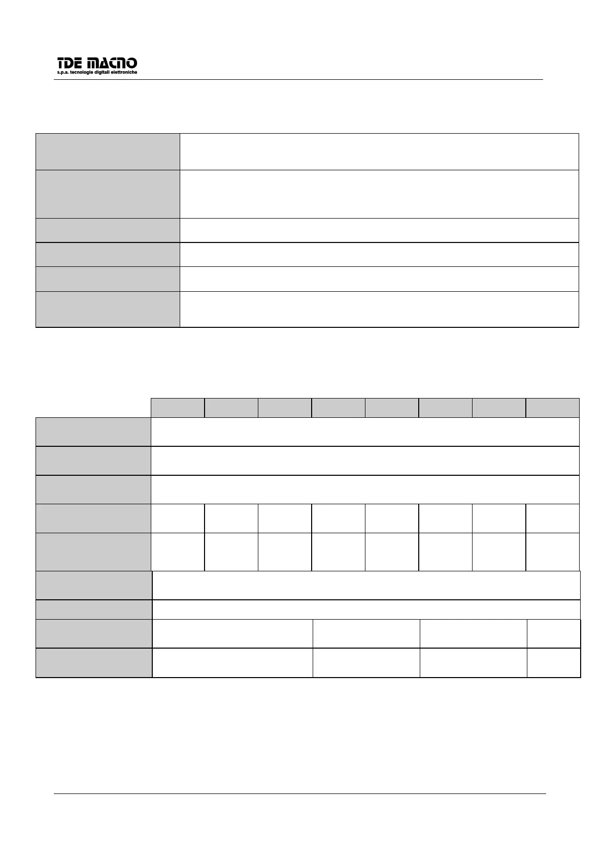
2.1.2. POWER CIRCUIT (DSC)
DSC-03N DSC-06N DSC-10N DSC-15N DSC-20N DSC-30N DSC-40N DSC-60N
INPUT VOLTAGE 3 x (140 - 240 ) Veff. 45-65 Hz
MAX OUTPUT VOLTAGE
(Veff)
3 x Vi x 0.9 (Vi = input voltage)
OUTPUT FREQUENCY 0 - 400 Hz
NOMINAL RMS CURRENT
( A ) 3.5 6 10 15 20 30 40 60
MAX RMS CURRENT ( A )
100 ms for f=0
2.5 s for f>2.5 Hz
7 122030406080120
CLAMPING VOLTAGE 380 V c.c.
OVERVOLTAGE LEVEL
( V )
410
MAX PEAK CURRENT
(t<0.3 sec.) ( A )
15 25 38 50
MINIMUM VALUE OF
RESISTIVE LOAD
Ω
(W)
27 (100W) 15 (200W) 10 (300W) 15 (200 W)||
15 (200 W)