User manual 14-1
DSC/DSCT Series
14. FREQUENCY INPUT(OPTIONAL)
The brushless digital drives have an optional frequency input. (it’s necessary specify this in the commercial
order). So it’s possible to have an analog reference speed (J2-11 e J2-12) or a frequency reference speed
(connector J6) by selecting on software switch C14.
c14 working mode
0 analog reference (default)
1 frequency reference (encoder)
2 frequency reference (freq. and up/down)
With
P10
=0 the motor speed is proportional to the input frequency.
With
P10
>0 the motor speed is proportional to the input frequency and an internal space loop is activated
(proportional gain=P10) so every input pulse corrisponde to a partial motor rotation. Maximum allowed error
is 32750 pulses; errors greater than this are not considered.
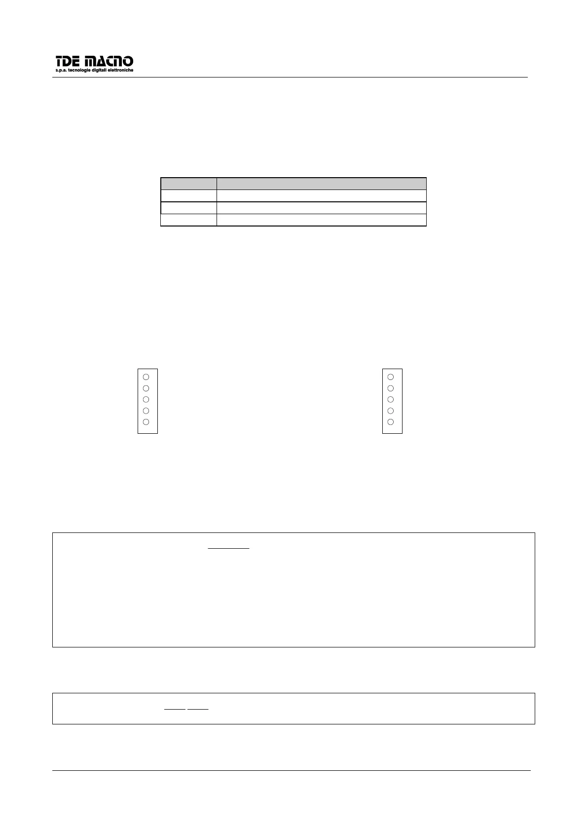
• frequency input as standard encoder (TTL
signals)
• frequency input by only two single channels
(unipolar signals with amplitude from 5V to 24V)
Maximum frequency speed reference: 300khz.
J6
5
4
3
2
1
CHANNEL A
CHANNEL /A
CHANNEL B
CHANNEL /B
0DG
J6
1
2
3
4
5
N.C.
FREQUENCY
N.C.
UP/DOWN
0DG
If the signal UP/DOWN = 0V the displayed speed is positive (D5>0) and the motor turns CW.
If the signal 0V< UP/DOWN <= 24V the displayed speed is negative (D5<0) and the motor turns CCW.
The desired speed can be obtained from an input frequency
Fr
by setting
P61
as follows:
14
60
4096
61
c
Fr
N
RPMP
slave
⋅
⋅
⋅
⋅=
,
slave
RPM
desired speed of the slave at the frequency
Fr
N number of encoder pulses/elctrical rev. (set in c11)
Fr
input frequency
c
14
connection c14
If the input frequency is genearted from a DSC/DSCT as master drive (the following par. are in the master
drive):
2
54
60
52
PP
NFr
=