To minimize the noise pickup or r
diation, the load wires and remote sense wires should be twisted
pairs to the shortest possible length. Shielding of sense leads may be necessary in high noise
ronments. Where shielding is used, co
nect the shield to the chassis via a rear panel Ground screw.
Even if noise is not a concern, the load and remote sense wires should be twisted
pling, which might impact the stability of power su
pply. The sense leads should be sep
Twisting the load wires reduces the parasitic inductance of the cable, which could produce high fr
quency voltage spikes at the load and the output of power supply, because of current variati
The impedance introduced between the power supply output and the load could make the ripple and
noise at the load worse than the noise at the power supply rear panel output. Additional filtering with
bypass capacitors at the load te
minals may be required to bypass the high frequency load current.
Inductive loads can produce voltage spikes that may be harmful to the power supply. A diode should
be connected across the output. The diode voltage and current ratin
g should be greater than the power
supply maximum output voltage and current rating. Connect the cathode to the positive output and the
anode to the negative output of the power supply.
Where positive load transients such as back EMF from a motor may occur
sor across the output to protect the power supply. The breakdown voltage rating of the suppressor
proximately 10% higher than the maximum output voltage of the power supply.
Connecting single loads, local sensing (defaul
10 shows recommended load and sensing connections for a single load. The local sense lines
shown are default connections at the rear panel J2 sense connector. Local sensing is suitable for a
plications where load regul
10: Single load connection, local sensing
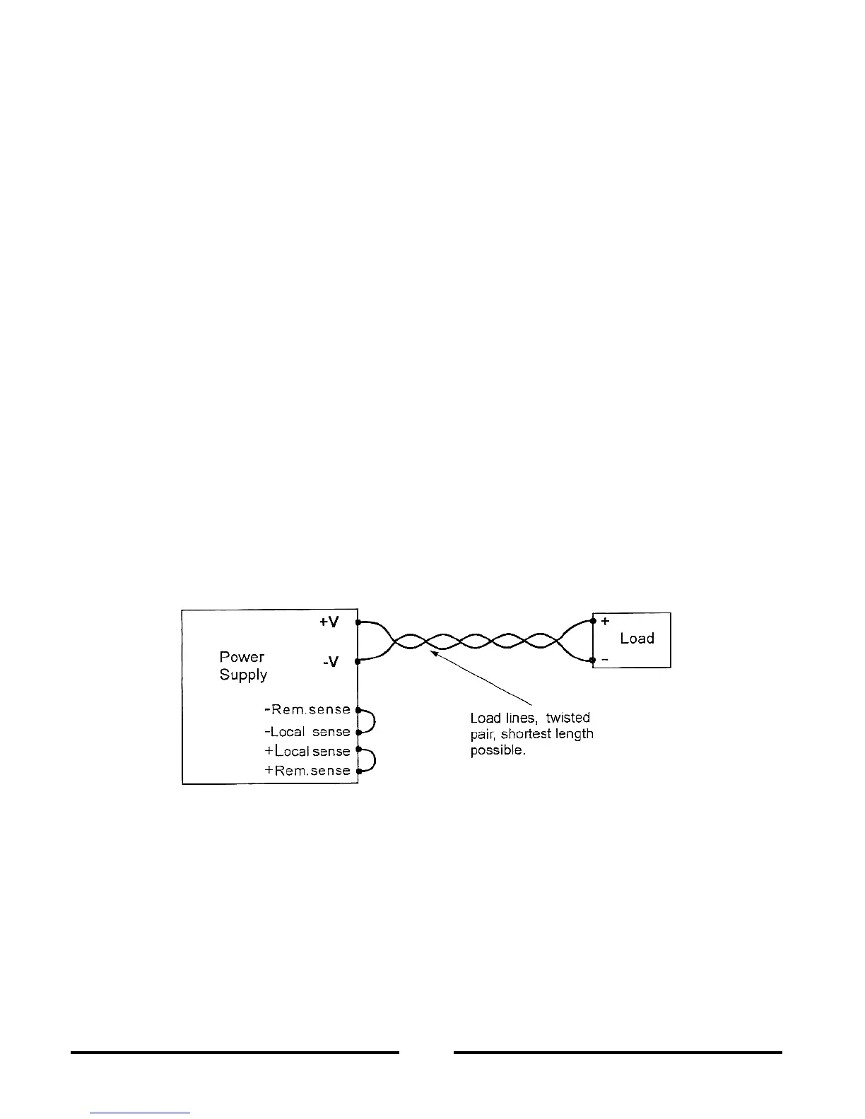
Connecting single loads, remote sensing
11 shows recommended remote sensing connection for single loads. Remote sensing is used
stant Voltage mode, the load regulation is important at t
he load terminals. Use twisted or
shielded wires to minimize noise pick
up. If shielded wires are used, the shield should be connected to
the ground at one point, either at the power supply chassis or the load ground. The optimal point for
d should be determined by experime