39
3.10 Local and Remote Sensing
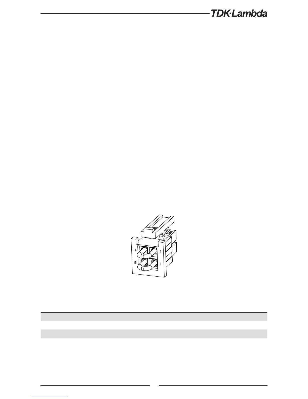
The rear panel J2 sense connector is used to configure the power supply for local or remote sensing
of the output voltage. Refer to Fig.3-10 for sense connector location.
3.10.2 Local Sensing
The power supply is shipped with the rear panel J2 sense connector wired for local sensing of
the output voltage. Refer to Table 3-4 for J2 terminals assignment. With local sensing, the output
voltage regulation is made at the output terminals. This method does not compensate for voltage
drop on the load wires, therefore it is recommended only for low load current applications or
where the load regulation is less critical.
3.10.1 Sense Wiring
Fig.3-10: Sense connector location
WARNING:
There is a potential shock hazard at the sense connector when using a power supply with an output
voltage greater than 42.4V. Local sense and remote sense wires should have a minimum insulation
rating equivalent or greater than the maximum output voltage of the power supply. Ensure that the
connections at the load end are shielded to prevent accidental contact with hazardous voltages.
WARNUNG:
Bei Einsatz eines Netzteils mit einer Ausgangsspannung von mehr als 42,4 V. besteht Stromschlaggefahr.
Lokale Anschlüsse und Remote-Sense-Leitungen sollten eine minimale Bemessungsisolationsspannung,
entsprechend oder größer als die maximale Ausgangsspannung der Stromversorgung, haben.
Stellen Sie sicher, dass die Anschlüsse an der Last abgeschirmt sind, um versehentlichen Kontakt mit
gefährlichen Spannungen zu verhindern.
Terminal Function
J2-1 Local negative sense. Connected internally to the negative output terminal (-LS).
J2-2 Remote negative sense (-S).
J2-3 Remote positive sense (+S).
J2-4 Local positive sense. Connected internally to the positive output terminal (+LS).
Table 3-4: J2 terminals