58
5.5 Parallel Operation
5.5.1 Introduction
Up to six units of the same Voltage and Current rating can be connected in parallel to provide up
to six times the output current capability. One of the units operates as a master and the remaining
units are slaves. The slave units are analog programmed by the master unit. In remote digital
operation, only the master unit can be programmed by the computer while the slave units may
be connected to the computer for voltage, current and status readback only.
The Master and Slave modes are stored in the power supply EEPROM when the AC power is turned
off. The system will return to the Master/Slave mode upon re-application of AC power.
There are two methods to configure multiple supplies for parallel operation (basic and advanced).
Refer to Section 5.5.2 and to Section 5.5.3 for detailed explanation. Parallel modes are selected
via Front Panel menu. Refer to table 5-2.
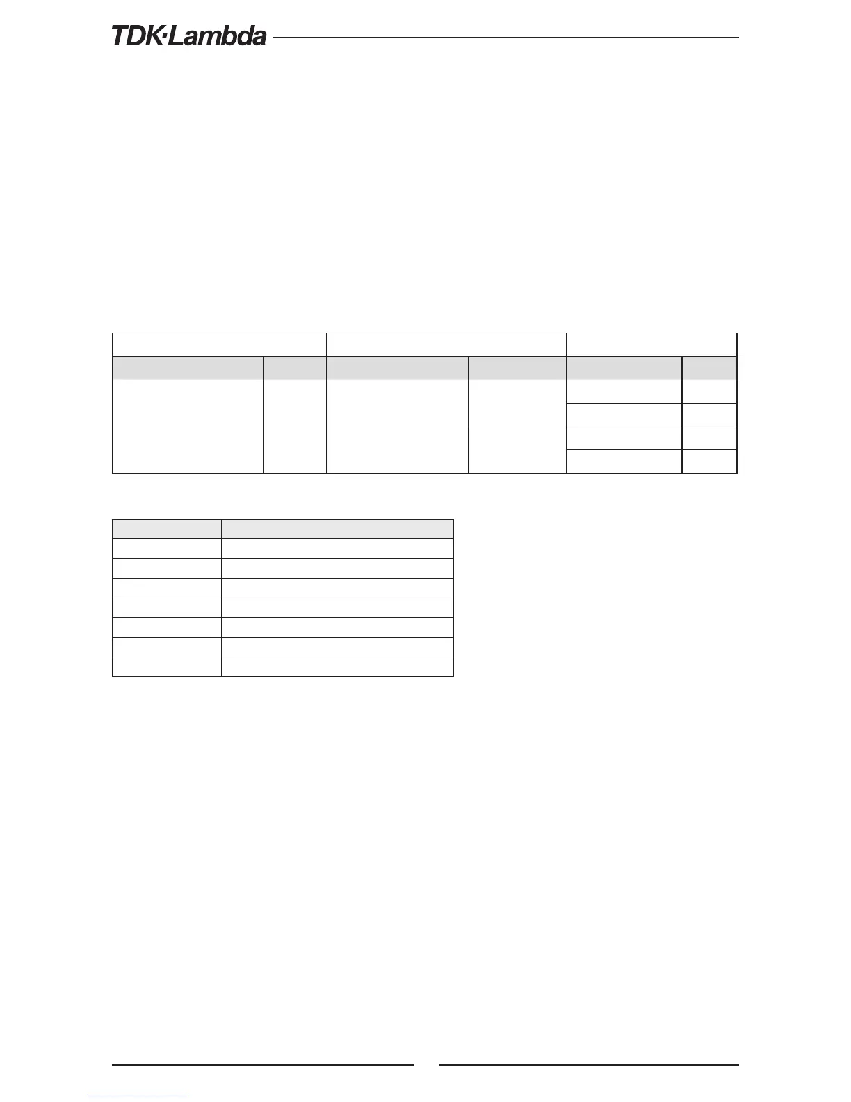
Subsystem Level Function Level Parameter Level
Description Display Function Display Description Display
Parallel Operating Mode
r
Host /Basic Slave /
Advanced Slave
Hot
Master (Basic)
H1
Master (Advanced)
H2
..
H
Se
Slave (Basic)
S
Slave (Advanced)
SAD
Table 5-2. Parallel subsystem menu
5.5.2 Basic Parallel Operation
In this method, setting the units as Master and Slaves is made by the rear panel J1 connections
and setup via Front Panel. Each unit displays its own output current and voltage. To program the
load current, the Master unit should be programmed to the total load current divided by the
number of units in the system. Refer to the following procedure to configure multiple supplies
for simple parallel operation.
5.5.2.1 Master Unit Set Up
Set the master unit output voltage to the desired voltage. Program the current limit to the desired
load current limit, divided by the number of parallel units. During operation, the master unit
operates in CV mode, regulating the load voltage at the programmed output voltage. Connect
the sensing circuit to local or remote sensing as shown in Fig.5-4 or Fig.5-5. Front Panel Main Menu
Parallel mode is "H1” as default.
1. Press MENU button.
2. Rotate Voltage Encoder until “r” appears on Voltage display, then press Voltage Encoder.
3. Rotate Current Encoder until “H1 ” appears.
4.
Press Current Encoder to select “H1 ”, the display blinks once and returns to previous menu level.
Display Operating Mode
H1
Single Supply (default)
H2
Master Supply with 1 Slave supply
H3
Master Supply with 2 Slave supply
H4
Master Supply with 3 Slave supply
H5
Master Supply with 4 Slave supply
H
Master Supply with 5 Slave supply
S
Slave Supply
Table 5-2.1: Operation Setting Mode