83
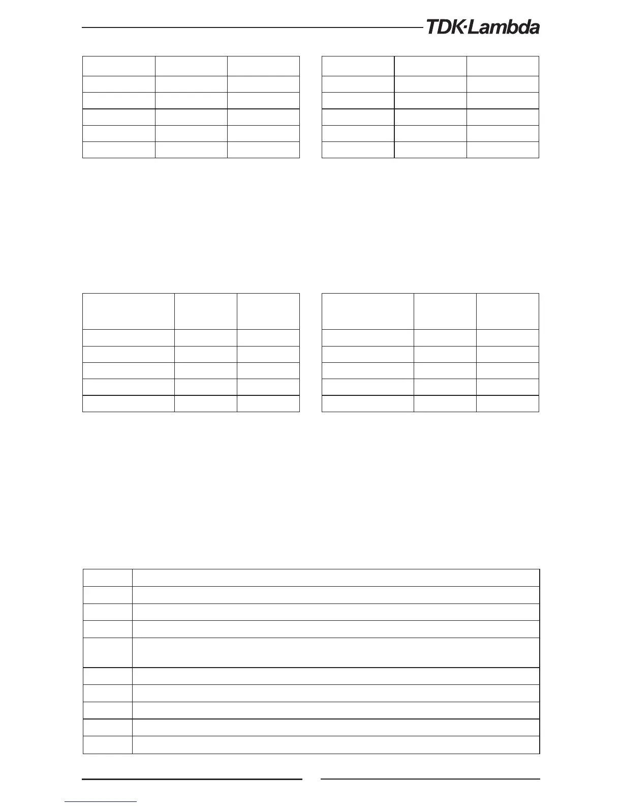
Model Rated Output
Voltage (V)
Minimum (V) Maximum (V)
10 0.5 12.0
20 1.0 24.0
36 2.0 40.0
60 5.0 66.0
100 5.0 110
Table 7-8: OVP programming range
Model Rated Output
Voltage (V)
Minimum (V) Maximum (V)
10 0 9.5
20 0 19.0
36 0 34.2
60 0 57.0
100 0 95.0
Table 7-9: UVL/UVP programming range
Model Minimum (A) Maximum (A)
10-20 00.00 20.00
20-10 00.00 10.00
36-6 0.000 6.000
60-3.5 0.000 3.500
100-2 0.000 2.000
Table 7-6: Z200 models Current programming range
Model Minimum (A) Maximum (A)
10-40 00.00 40.00
20-20 00.00 20.00
36-12 00.00 12.00
60-7 0.000 7.000
100-4 0.000 4.000
Table 7-7: Z400 models Current programming range
NOTE:
The power supply can accept values higher by 5% than the table values, however it is not recommended
to program the power supply over the rated values.
NOTE:
The UVP protection starts operating for values higher than 5% of Rated Output Voltage.
7.8.7 Auxiliary Commands
SOP Sets SO polarity “SO 1/ON” –Positive (default), “SO 0/OFF”-Negative
SOP? Returns the SO polarity
RIE Remote inhibit (Interlock) enable. “RIE 1/ON”-Enable, “RIE 0/OFF”-Disable”
RIE? Returns the RIE polarity. “ON” –interlock enable, “OFF”-interlock disable.
FRST
Factory reset command. This command cover *RST command and additional settings. Sets factory
default. This command breaks communication. Refer to Table
5-7.
MP? Reads the actual output power. Returns 5 digit string.
REL1 Set auxiliary programmed pin state J3-1. “REL1 1/ON”- High, REL1 0/OFF”- Low
REL1? Response auxiliary programmed pin state J3-1.
REL2 Set auxiliary programmed pin state J3-6, “REL2 1/ON”- High, REL2 0/OFF”- Low
REL2? Response auxiliary programmed pin state J3-6