64
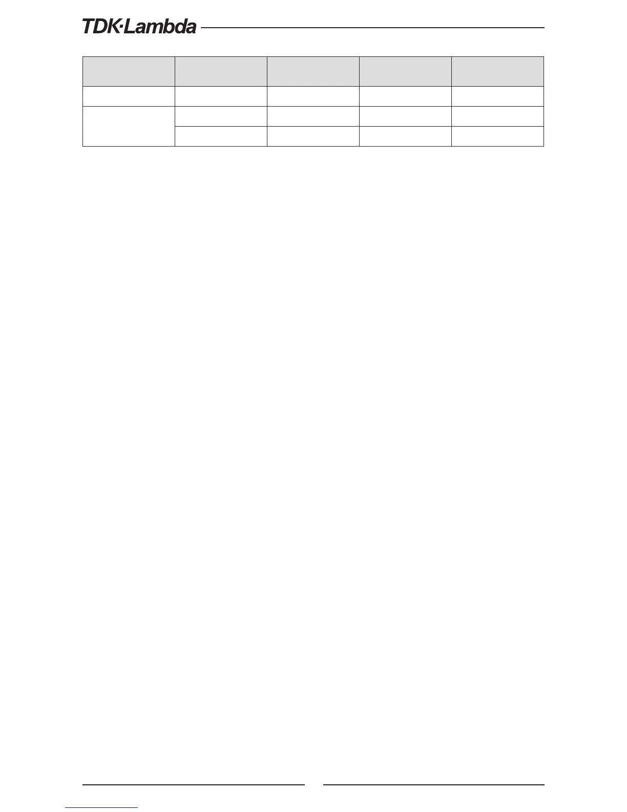
Front Panel ILC
Setting
ILC Input
Power Supply
Output
Display Alarm LED
OFF - Default Open or Short On Voltage/Current Off
ON
Open Off
ENA
Blinking
Short On Voltage/Current Off
Table 5-5: Interlock functions and settings
CAUTION:
To prevent possible damage to the unit, do not connect any of the Enable /Disable inputs to the
positive or negative output potential.
NOTE:
Safe Start mode - If the Interlock fault condition clears while units are in safe start mode, the power
supply returns to Off mode.
Auto Restart mode - The output will automatically return to previous state.
5.7.3 Auxiliary Programmed Function Pin 1 and Pin 2
The programmed signal Pin 1 (J3-1) and Pin 2 (J3-6) are open collector, maximum input voltage
25V and maximum sink current 100mA, and can be controlled via Front panel or software.
Pin 1 or Pin 2 settings are made as follows:
1. Press MENU button. MENU (GREEN) LED illuminates. The “r
.
AN” message appears on the
Current display.
2. Press Current Encoder and the “I C ” message appears on the Voltage display.
3. Rotate Voltage Encoder until “i 1 / i 2” message appears on display. Press Encoder to
select the desired Pin.
4. Voltage display shows the selected Pin number.
5. Rotate the Current Encoder to toggle between “Hi ” (High) or “o” (Low).
6. Press Current Encoder to select desired parameter.
7. Press MENU button twice to return display to it’s previous state. MENU LED turns OFF.
CAUTION:
Do not connect Pin 1 and Pin 2 to a voltage source higher than 25V. Always connect Pin 1 and Pin 2
to the voltage source with a series resistor to limit the sink current to less than 100mA.