62
5.6 Daisy-Chain Connection
It is possible to configure a multiple power supply system to shut down all units when a fault
condition occurs in one of the units. When the fault is removed, the system recovers according to
a preset state: Safe start mode or Automatic restart.
Set signal “SO” to positive logic via Front panel (refer to section 5.7.1) . If a fault occurs in one of
the units it’s “PS_OK” signal will be set to low level and the display will indicate the fault. The other
units will shut off and their displays will indicate “SO”. When the fault condition is removed, the
units will recover to their last setting according to their respective Safe start or Auto-restart setting.
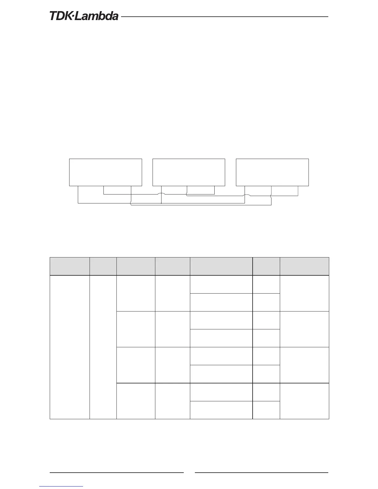
Fig.5-6 shows connection of three units, however the same connection method applies to systems
with more units.
Fig.5-6: Daisy-Chain connection
P OWE R S UP P LY
#1
J3-7
J3-2
J3-5
IF C_C OM PS _OK
S O
P OWE R S UP P LY
#2
J3-7
J3-2
J3-5
IF C_C OM PS _OK
S O
P OWE R S UP P LY
#3
J3-7
J3-2
J3-5
IF C_C OM PS _OK
S O
5.7 Rear Panel (J3 Connector) Functions and Settings
Subsystem
Level
Display
Function
Level
Display Parameter Level Display Description
Rear Panel
R
.
AN
Interlock
IC
Enable (ON)
O
Enable/Disable
iner- lock
function (Analog
ON/OFF)
Disable (OFF)
OFF
Shut OFF
SO
Positive
OS
Positive (polarity)
same such PS_OK
signal
Negative
NEG
Programmed
PIN 1
i1
High
Hi
Open collector
Low
o
Programmed
PIN 2
i2
High
Hi
Open collector
Low
o
Table 5-3: Rear panel subsystem menu