43
4.3 Rear Panel Connectors
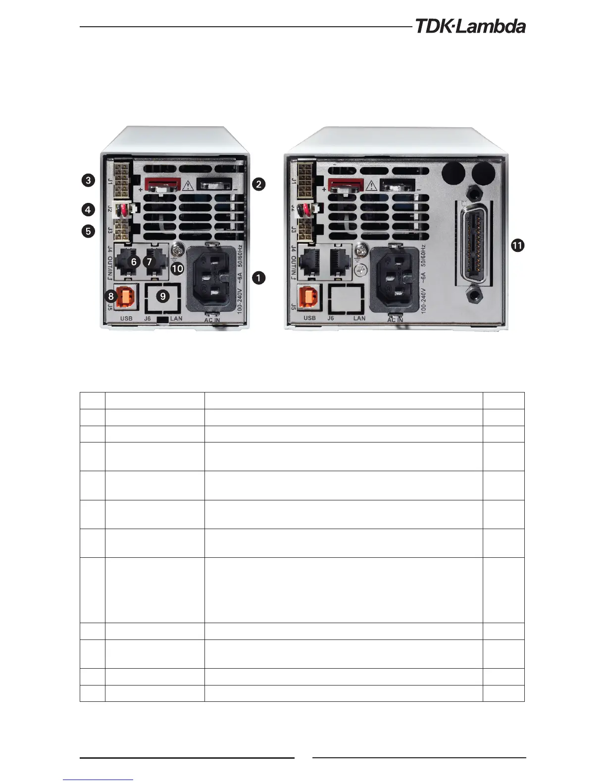
Refer to Fig.4-2 and Table 4-2 for description of the Rear Panel connectors.
No. Connection Description Section
1 AC Input Connector IEC320-16 TYPE CONNECTOR
2 DC output bus-bar Bus-bars for 10V to 100V models. Use M6 or 1/4” screws. 3.9.9
3
Analog Control and
signals. J1
Connector for remote analog interface. Analog control and monitoring.
Referenced internally to output potential -S.
4.3.1
4
Local/Remote sense
connector J2
Connector for making remote sensing connections to the load for
regulation of the load voltage and compensation of load wire drop.
3.8.1
3.10.2
5
Isolated control and
signal. J3
Control and monitoring signal, isolated from the output potential. 4.3.2
6
Remote Serial Out
connector
RJ-45 type connector, used for chaining power supplies to/from a serial
communication bus.
7.3
7
Remote Serial In
connector
RJ-45 type connector, use for connecting power supplies to RS232 or
RS485 port of computer for remote control purposes. When using several
power supplies in a power system, the first unit Remote-In is connected
to the computer and the remaining units are chained, Remote-In to
Remote-Out.
7.3
8 USB Connector USB interface connector, type B
9
LAN Connector
(optional)
LAN interface connector, type RJ-45
10 Ground screw M4x10 for chassis Ground connection
11 Optional Interface Position for GPIB Interface (shown) or Isolated Analog Interface.
Table 4-2: Rear panels connecions
Fig. 4-2: Rear panel connections