TECDrive20-EU Series Inverter Function parameters
-43-
and the inverter will coast to stop.
P01.04
ACC
P1314.
P0123.
Constant
speed
In running
DEC
P0110.
P1315.
P01.12
P01.09
t
Setting range of P01.09: 0.00Hz –P00.03
(the max. frequency)
Setting range of P01.10: 0.00–50.00s
Setting range of P01.11: 0.0–100.0% (rated
current peak of the inverter)
Setting range of P01.12: 0.00–50.00s
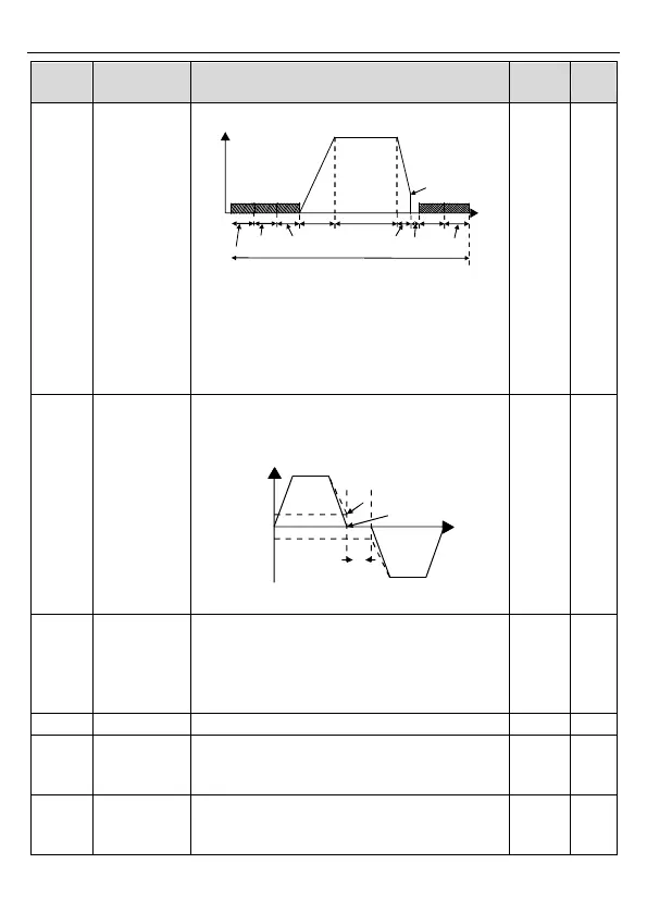
FWD/REV
running
deadzone time
This function code indicates the transition time
specified in P01.14 during FWD/REV rotation
switching. See the following figure.
Output frequency
FWD
REV
T
Starting
frequency
Shift after the
zero frequency
Shift after the
starting frequency
Setting range: 0.0–3600.0s
Set the threshold point of the inverter:
0: Switch at zero frequency
1: Switch at the start frequency
2: Switch after the speed reaches the stop speed
(P01.15) for the set the delay (P01.24)
Detection of
stopping speed
0: Detect at the setting speed
1: Detect at the feedback speed (valid only for
vector control only)
Detection time
of the feedback
speed
When P01.16=1, the actual output frequency of
the inverter is less than or equal to P01.15 and is
detected during the time set by P01.17, the