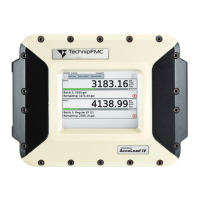
Do you have a question about the TechnipFMC Sening MultiLevel and is the answer not in the manual?
Explains the use of pictograms and manual structure for user guidance.
Crucial steps and precautions for safe and effective installation.
Safety instructions to prevent accidents related to gas explosions during installation.
Guidance on complying with electrical installation and wiring standards.
Best practices for ensuring long-term, reliable operation of the system.
Recommendations for easy access and maintenance of installed components.
Guidelines for proper cable management during vehicle installation.
Troubleshooting common operational errors and system behavior.
Instructions for operating the system in loading mode via remote access.
Steps for operating the system in delivery mode via remote access.
Overview of the system's electrical components and their interconnections.
Details on the physical parts and assembly of the level gauging system.
Explains how the level gauging system operates to measure liquid levels.
Requirements for ensuring the system meets calibration standards.
Describes the magnetostrictive sensor technology used for height measurement.
Details on how gauge tables are used for volumetric measurement and calibration.
How the system corrects measurements based on vehicle inclination.
Proper procedures for packing level sensors to prevent transport damage.
Guidelines for safely transporting level sensors to avoid bending or damage.
Details on the construction and components of the level sensor head.
Explanation of how sensor length is defined and marked.
Technical specifications and installation requirements for mechanical components.
Overview of the central control unit and its functions in the system.
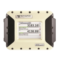
Details on the display and keyboard interface of the main unit.
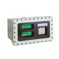
Information about the display and interface module for NoMix.
Explains the meaning of symbols and functions of the display interface keys.
Highlights key system functions and essential settings for operation.
Describes how MultiLevel interacts with the NoMix system for loading and delivery.
Configuration and operation of the system in stand-alone mode without NoMix.
Functionality and installation of the wet leg sensor interface.
Details on the NS-2E wet leg sensor, its installation, and adjustment.
Specifications and function of the MLDTS-2 temperature sensor.
Role of the MLIF interface in evaluating sensor data and system structure.
Description of the MLIS inclination sensor and its function.
Function and connection of the chip card reader for data storage.
Purpose of the I/O interface for controlling valves and system integration.
Steps for configuring the display interface and performing tests.
Detailed explanation of the loading menu and its functions.
Guide to navigating and operating the delivery menu.
How to access and use the print menu for various reports.
Accessing and printing the system's parameter setup information.
Printing gauging and slope tables for system calibration and data.
Accessing and printing various logbook entries like events and parameters.
Generating and printing tour reports, including examples.
Navigating the main menu to access and modify system settings.
Configuring display settings like date, time, and language.
Viewing the loading plan and product selection in stand-alone mode.
Accessing and understanding the system's detailed parameter list.
Configuration of device-specific parameters for system operation.
Setting compartment-specific parameters for the tank truck.
Configuration of various operating options and system behavior.
Defines parameters related to calibration and slope restrictions.
Configuration of printer-specific settings and interface options.
Access to service functions like seal management, diagnosis, and updates.
Explains how forms are structured using receipt elements and their properties.
Details on defining receipt elements, character representation, and custom texts.
Guidance on using the input dialogue for form customization.
Provides a systematic approach to diagnosing and resolving system faults.
Lists and explains information, error, and seal breakage messages.
Displays general information messages and their meanings.
Lists system error messages and their possible causes and corrections.
Explains messages related to seal status and parameter integrity.
Overview of general system specifications, approvals, and ranges.
Technical specifications for the main unit and display module.
Technical details for the Level Gauge Interface LLGIF.
Specifications for the LLGIS inclination sensor.
Technical data for the LLGDTS-2 temperature sensor.
Technical specifications for the Level Sensor Interface.
Technical details for the S-NS-2... Level Sensor.
Specifications and interface details for the printer.
Information regarding electrical device inspections and related regulations.
Guidelines for device maintenance and safety checks.
Procedures for replacing software components, including the main unit EPROM.
Information on replacing interface module microprocessors if software needs updating.
Steps and procedures for downloading and updating system software.
Explains memory organization and checksums without software separation.
Describes memory organization with separated calibration/non-calibration data.
Step-by-step process for updating the system software.
Detailed instructions for performing software updates via PC or SD card.
Using the service tool for accessing and configuring MultiLevel functions.
Records of software versions, changes, and revisions over time.
Configuration settings for the DR-298 printer's DIL switches.
Configuration settings for the DR-295 printer's DIL switches.
Configuration settings for the DR-220 printer's DIL switches.
Instructions for correctly assembling EMC cable glands for secure connections.
Hierarchical view of device settings parameters and their configuration.
Detailed settings for compartments, including number and monitoring options.
Specific parameters for individual compartments, including sensors and installation.
Further compartment data, W&M limits, and preset values.
Configuration options for system operation, delivery, and loading.
Settings for volume preset, type, and auto-adjustment features.
Configuration of help screen content for delivery and other information.
Parameters that restrict calibration based on slopes and printer settings.
Settings related to printer selection, interface, and options.
Configuration parameters for printer drivers, including size and attributes.
Comprehensive list of all system parameters, their factory settings, and meanings.
Detailed parameter breakdown for each compartment, including sensors and data.
Parameters related to form layout, product definition, and compensation.
Information on product-specific parameters, names, and codes.
Defines the content and mapping of help displays shown during operation.
Lists and describes the available help displays and their corresponding IDs.
Lists factory-default products with their associated physical and compensation data.
Lists all available part numbers and drawings for system components.
Documents related to EC declarations of conformity and ATEX certifications.
| Brand | TechnipFMC |
|---|---|
| Model | Sening MultiLevel |
| Category | Measuring Instruments |
| Language | English |

