Performance
Check-2445A/2455A
Service
8.
Push
the upper TRIGGER MODE button to
enable CTT period measurements.
The
CTT period readout will appear
on
the left side
of
the upper line of readout.
The
word • SET" will appear next
to the readout delay value. This denotes the indirect mea-
surement
mode
of
Delta Time, simulating a non-CTT
scope.
b. Set the Time-Mark Generator for 20-ns markers.
Adjust the Vertical VOL TS/DIV as required for a display of
3 to 6 divisions.
c. Adjust the
A
REF
OR
DL Y
POS
control for a readout
display of DL
Y 21.25
ns
.
d. Adjust the Horizontal POSITION control
CW
until the
trace stops moving, then CCW to display the leading edge
of the 2nd B sweep time marker near the graticule center.
This becomes the reference point for the following pro-
cedure. Set the Time-Mark Generator to 5
ns
and
adjust
the Vertical VOL TS/DIV
and
Trigger LEVEL
as
required.
e.
Press
and
release the At button to obtain the At
display.
Push
in
the SEC/DIV knob for B
SWP
only.
Rotate the
A control for a readout display
of
At
-20.0
ns.
If the time marks are not superimposed, adjust the A con-
trol to do
so.
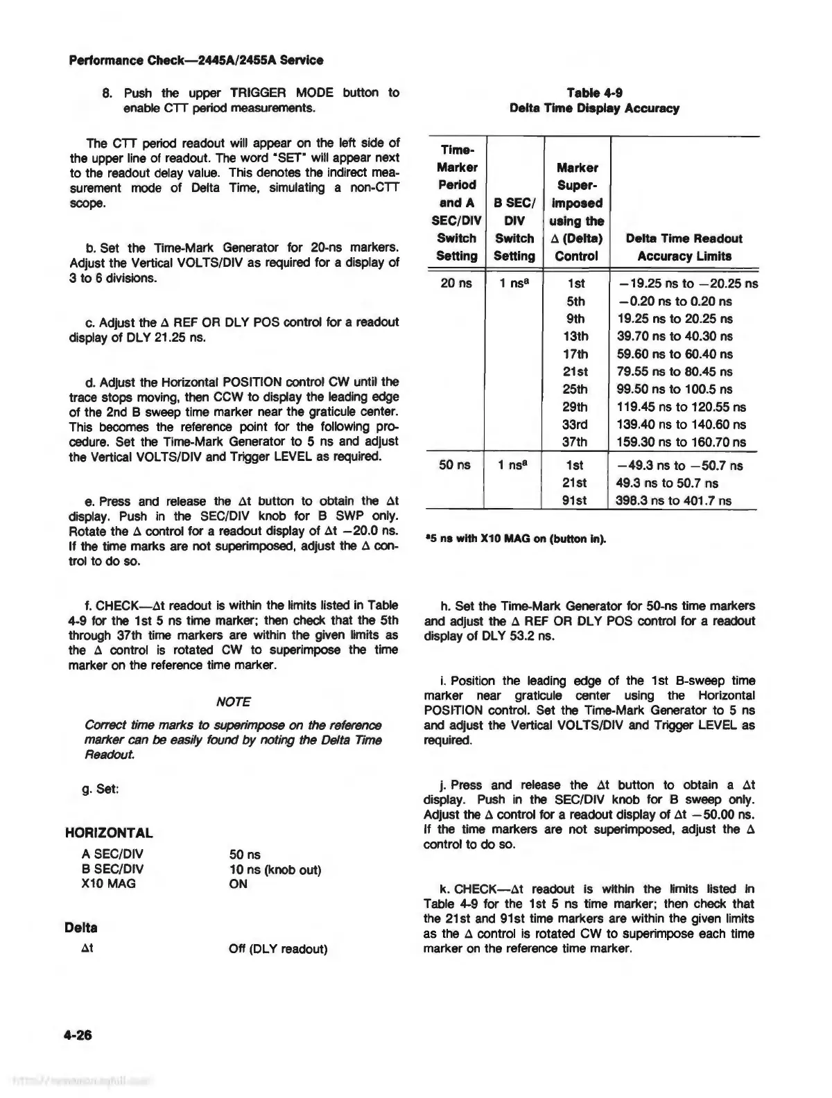
f.
CHECK-At
readout
is
within the limits listed
in
Table
4-9 for the 1st 5
ns
time marker; then check that the 5th
through 37th time markers are within the given limits
as
the A control
is
rotated
CW
to superimpose the time
marker
on
the reference time marker.
NOTE
Correct time marks to superimpose on the reference
marker can be easily found
by
noting the Delta Time
Readout.
g.
Set:
HORIZONTAL
A SEC/DIV
B SEC/DIV
X10
MAG
Delta
At
4-26
50
ns
10 ns (knob out)
ON
Off (DL Y readout)
Table 4-9
Delta Time Display Accuracy
Time-
Marker
Marker
Period
Super-
and A
B SEC/
imposed
SEC/DIV
DIV
using the
Switch Switch
A (Delta) Delta Time Readout
Setting Setting
Control Accuracy Limits
20 ns 1
ns
8
1st
-19.25
ns
to
-20.25
ns
5th
- 0.20
ns
to
0.20 ns
9th
19
.25
ns
to 20.25
ns
13th
39.70 ns to 40.30
ns
17th
59.60
ns
to
60.40
ns
21st
79
.55
ns
to 80.45
ns
25th
99.50 ns to 100.5
ns
29th 119.45
ns
to
120.55
ns
33rd
139.40
ns
to 140.60
ns
37th 159.30
ns
to 160. 70 ns
50
ns
1
ns
8
1st
-49
.3
ns
to
-50.7
ns
21st
49
.3
ns
to 50.7 ns
91st
398.3
ns
to
401. 7
ns
•s ns with X10 MAG
on
(button in).
h. Set the Time-Mark Generator for 50-ns time markers
and
adjust the A
REF
OR
DL Y
POS
control for a readout
display of
DL
Y 53.2
ns
.
i.
Position the leading edge of the 1 st B-sweep time
marker near graticule center using the Horizontal
POSfflON control. Set the Time-Mark Generator to 5
ns
and
adjust the Vertical VOL TS/DIV
and
Trigger LEVEL as
required.
j. Press and release the At button to obtain a At
display.
Push
in
the SEC/DIV knob for B sweep only.
Adjust the
A control for a readout display of At - 50.
00
ns
.
If the time markers are not superimposed, adjust the
A
control to do
so.
k.
CHECK-At
readout is within the limits listed
In
Table
4-9
for the 1st 5
ns
time marker; then check that
the 21st
and
91
st time markers are within the given limits
as the
A control
is
rotated CW to superimpose each time
marker
on
the reference time marker.