Maintenance-2445A/2455A
Service
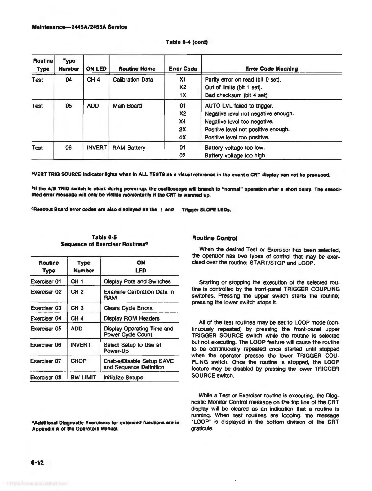
Table
8-4 (cont)
Routine
Type
Type
Number
ON
LED
Routine Name Error Code Error Code Meaning
Test
04
CH
4 Calibration Data
X1
Parity error on
read
(bit O set).
X2
Out of limits (bit 1 set).
1X
Bad
checksum (bit 4 set).
Test
05
ADD
Main Board
01
AUTO LVL failed to trigger.
X2
Negative level not negative enough.
X4
Negative level too negative.
2X
Positive
level
not positive enough.
4X
Positive
level
too positive.
Test 06
INVERT
RAM Battery
01
Battery voltage too low.
02
Battery voltage too high.
•VERT
TRIG
SOURCE
indicator lights when
In
ALL
TESTS
as a visual reference In
the
event a
CRT
display can not be produced.
blf the A/B
TRIG
switch is stuck during power-up, the oscilloscope will branch to
"nonnal"
operation after a short delay. The associ-
ated
error message will only
be
visible momentarily
if
the
CRT
Is wanned up.
cReadout Board error
code•
are also displayed on the + and - Trigger
SLOPE
LEDs.
Table 6-5
Sequence of Exerciser Routines•
Routine
Type
ON
Type Number
LED
Exerciser
01
CH
1 Display Pots and Switches
Exerciser 02
CH
2 Examine Calibration Data
in
RAM
Exerciser 03
CH
3
Clears Cycle Errors
Exerciser 04
CH
4 Display
ROM
Headers
Exerciser 05
ADD
Display Operating Time and
Power Cycle Count
Exerciser 06
INVERT
Select Setup
to
Use at
Power-Up
Exerciser
07
CHOP
Enable/Disable Setup SAVE
and Sequence Definition
Exerciser
08
BW
LIMIT
Initialize Setups
•Additional Diagnostic Exercisers for extended functions are
In
Appendix A of the Operators Manual.
6-12
Routine Control
When
the desired Test
or
Exerciser has
been
selected,
the operator has two types of control that may
be
exer-
cised over the routine: START/STOP and
LOOP.
Starting
or
stopping the execution
of
the selected rou-
tine
is
controlled by the front-panel TRIGGER COUPLING
switches. Pressing the upper switch starts the routine;
pressing the lower switch stops
it.
All
of
the test routines may
be
set to
LOOP
mode (con-
tinuously repeated) by pressing the front-panel upper
TRIGGER SOURCE switch while the routine
is
selected
but not executing.
The
LOOP feature will cause the routine
to
be
continuously repeated once started until stopped
when the operator presses the lower
TRIGGER
COU-
PLING switch. Once the routine is stopped, the
LOOP
feature may
be
disabled by pressing the lower
TRIGGER
SOURCE switch.
While a Test or Exerciser routine
is
executing, the Diag-
nostic Monitor Control message on the top line of the CRT
display will
be
cleared as an indication that a routine
is
running.
When
test routines
are
looping, the message
"LOOP"
is
displayed
in
the bottom division
of
the
CRT
graticule.