Performance
Check-2445A/2455A
Service
5.
Check Delay
From
Selected Edge
to
WORD
RECOG
OUT.
a.
Set:
VERTICAL
CH3
and
CH
4
CH
1,
CH
2,
ADD,
and
INVERT
CH
3 VOL TS/DIV
On
Off
0.1
V
(1
V with
X 1 0 probe attached)
HORIZONTAL
A
and
B SEC/DIV
20
ns
b.
Connect the instrument X10 probe to the
CH
4 input
connector
and
the probe tip to the wire
on
the
red
binding
post of the
CH
1 input.
c. Set pulse generator # 1 to produce a 50-ns positive
pulse every 10
µS.
d.
Set the A TRIGGER SOURCE to
CH
4.
e.
For
each
test setup described
in
Table 4-14:
1. Push the
~t
button.
2.
Tum the
~
REF
OR
DL Y
POS
control to align
the delta reference cursor with the active
edge
of
the channel 4 signal.
3. Turn the
~
control to align the delta cursor with
the rising edge of the channel 3 signal.
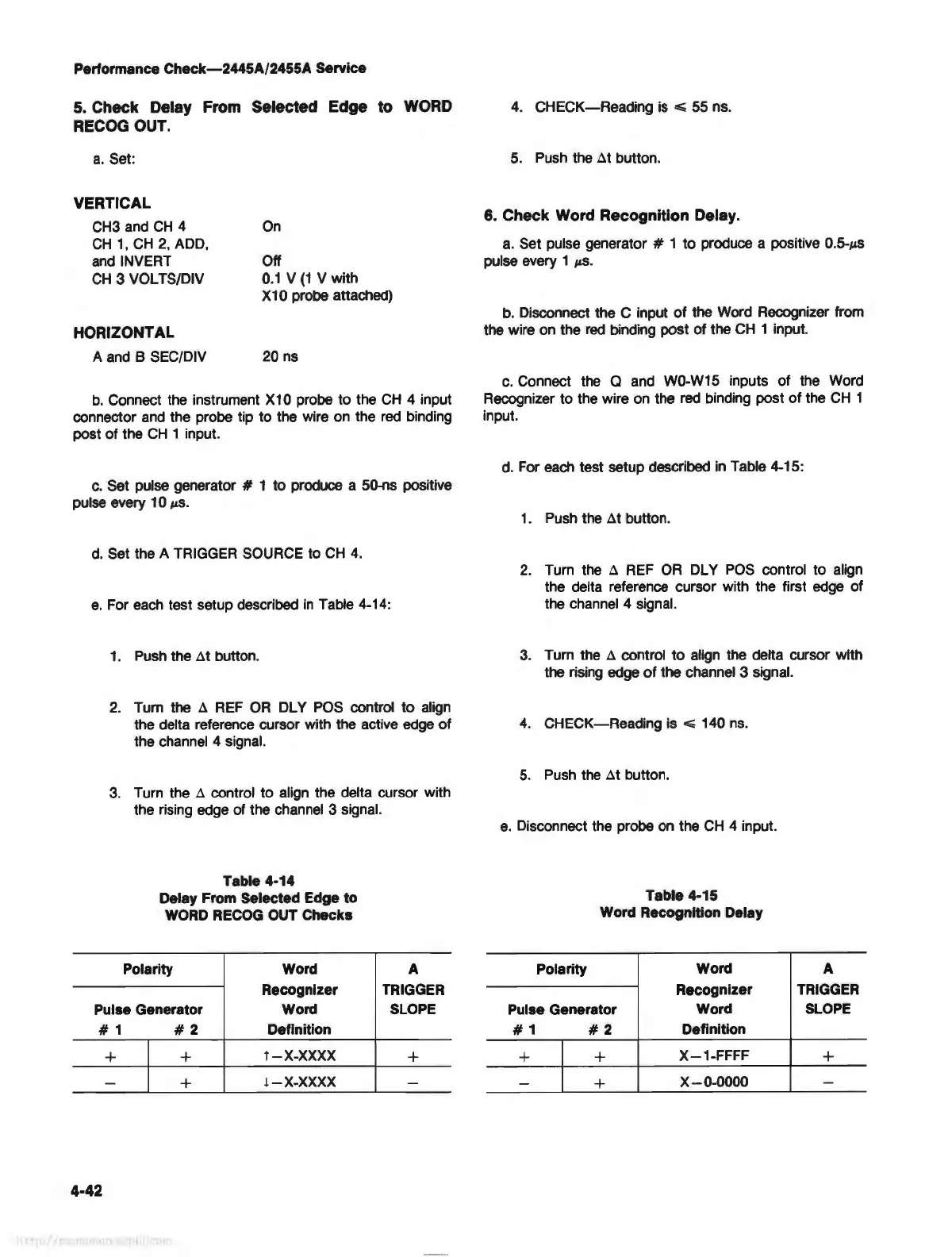
Table
4-14
Delay From Selected Edge to
WORD RECOG OUT Checks
Polarity Word
Recognizer
A
TRIGGER
Pulse Generator
Word SLOPE
#1
#2
Definition
+ +
T-X-XXXX
+
-
+
l-X-XXXX
-
4-42
4.
CHECK-Reading
is
~
55 ns.
5.
Push
the
~t
button.
6. Check Word Recognition Delay.
a.
Set pulse generator # 1 to produce a positive 0.5-µs
pulse every 1
µs.
b.
Disconnect the C input
of
the Word Recognizer from
the wire
on
the
red
binding post of the
CH
1 input.
c.
Connect the a and W0-W15 inputs of the Word
Recognizer to the wire
on
the
red
binding post
of
the
CH
1
input.
d.
For
each
test setup described
in
Table 4-15:
1.
Push
the
~t
button.
2.
Turn the
~
REF
OR
DL Y
POS
control to align
the delta reference cursor with the first edge of
the channel 4 signal.
3.
Turn the
~
control to align the delta cursor with
the rising edge
of
the channel 3 signal.
4.
CHECK-Reading is
...;
140
ns.
5.
Push
the
~t
button.
e.
Disconnect the probe
on
the
CH
4 input.
Table 4-15
Word Recognition Delay
Polarity
Word A
Recognizer TRIGGER
Pulse Generator
Word SLOPE
#1
#2
Definition
+ +
X-1-FFFF
+
-
+
X-0-0000
-