Adjustment
Procedure-2445A/2455A
Service
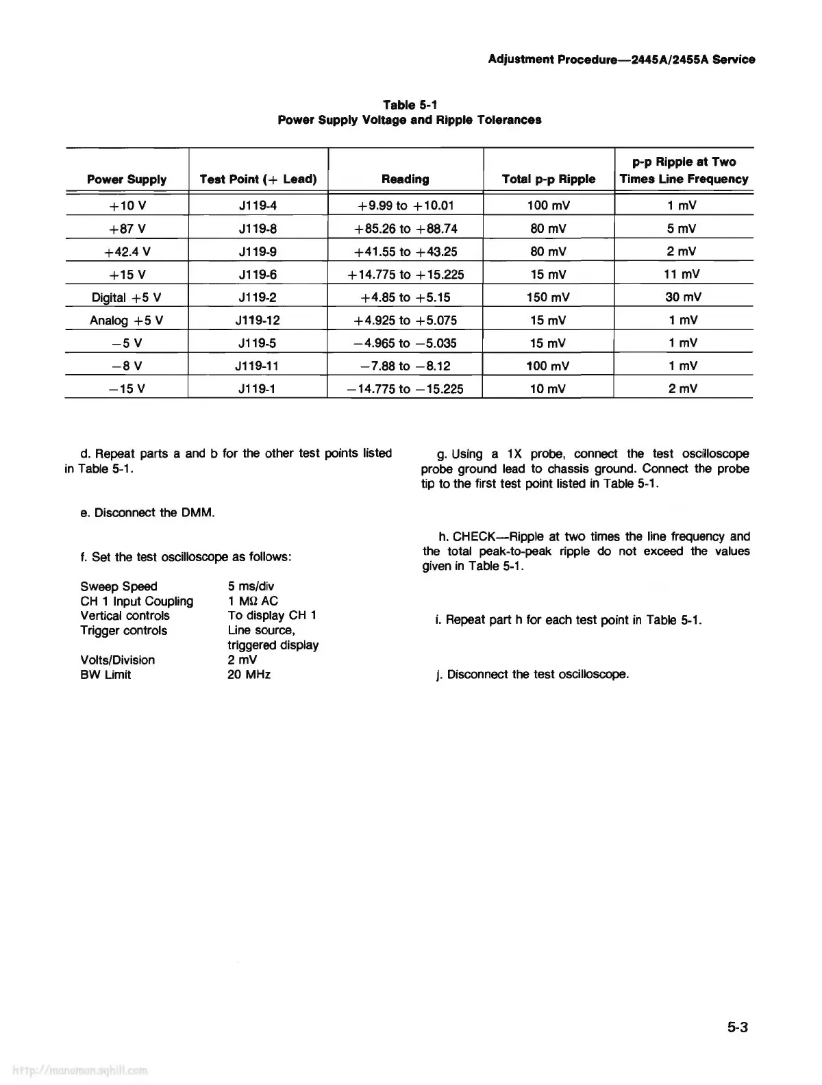
Table
5-1
Power Supply Voltage and Ripple Tolerances
p-p Ripple at Two
Power Supply Test Point (
+ Lead) Reading
Total p-p Ripple Times Line Frequency
+10v
J119-4
+9.99
to
+
10.01
100
mV
1
mV
+87V
J119-8
+85.26
to
+88.74
80
mV
5mV
+42.4
V
J119-9
+41.55
to
+43.25
80
mV
2mV
+15
V
J119-6 +14.775
to
+15.225
15
mV
11
mV
Digital
+5
V
J119-2
+4.85
to
+5.15
150 mV
30mV
Analog
+5
V
J119-12
+4.925
to
+5.075
15
mV
1
mV
-5V
J119-5
-4.965
to
-5.035
15
mV
1
mV
-8V
J119-11
-7.88
to
-8.12
100 mV
1
mV
-15
V J119-1
-14.775
to
-15.225
10
mV
2mV
d. Repeat parts a
and
b for the other test points listed
in
Table 5-1.
g.
Using a 1 X probe, connect the test oscilloscope
probe ground
lead
to
chassis ground. Connect the probe
tip
to
the first test point listed
in
Table 5-1.
e.
Disconnect the DMM.
f.
Set the test oscilloscope as follows:
Sweep Speed
CH
1 Input Coupling
Vertical controls
Trigger controls
Volts/Division
BW Limit
5 ms/div
1 Mil
AC
To display
CH
1
Line source,
triggered display
2mV
20 MHz
h.
CHECK-Ripple
at
two
times the line frequency
and
the total peak-to-peak ripple do not exceed the values
given
in
Table 5-1.
i.
Repeat part h for each test point
in
Table 5-1.
j. Disconnect the test oscilloscope.
5-3