Maintenance-2445A/2455A
Service
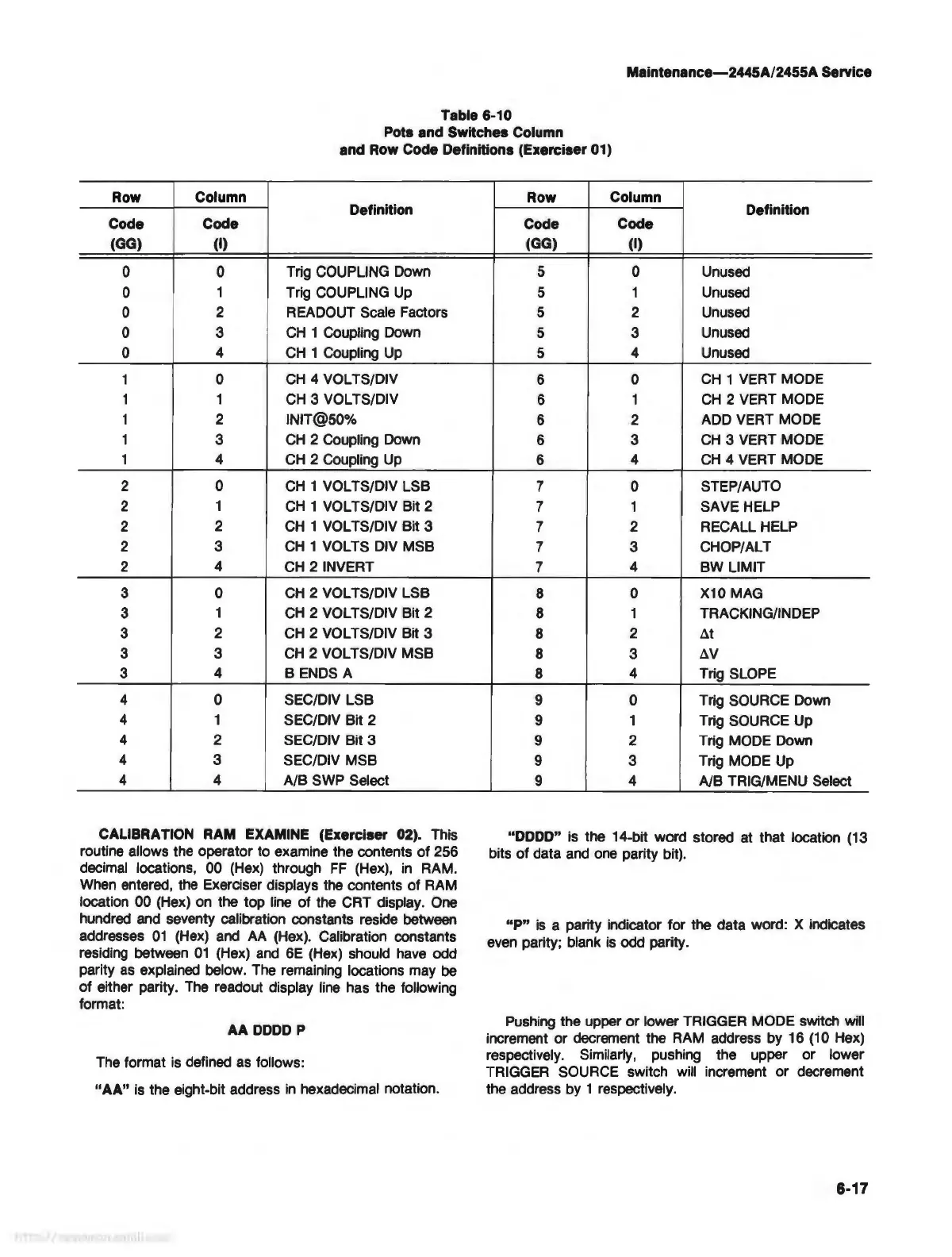
Table 6-10
Pots and Switches Column
and Row Code Definitions (Exerciser 01)
Row Column
Definition
Code Code
(GG) (I)
0
0
Trig COUPLING Down
0
1
Trig COUPLING
Up
0 2 READOUT Scale Factors
0
3
CH
1 Coupling Down
0 4
CH
1 Coupling
Up
1 0
CH
4 VOL TS/DIV
1 1
CH
3 VOL TS/DIV
1
2
INIT@50%
1
3
CH
2 Coupling Down
1
4
CH
2 Coupling
Up
2
0
CH
1 VOL TS/DIV LSB
2 1
CH
1 VOL TS/DIV Bit 2
2 2
CH
1 VOL TS/DIV Bit 3
2
3
CH
1 VOL TS DIV MSB
2
4
CH
2 INVERT
3
0
CH
2 VOL TS/DIV LSB
3
1
CH
2 VOL TS/DIV Bit 2
3 2
CH
2 VOL TS/DIV Bit 3
3
3
CH
2 VOL TS/DIV MSB
3
4
BENDS
A
4
0 SEC/DIV LSB
4
1
SEC/DIV Bit 2
4
2
SEC/DIV Bit 3
4
3
SEC/DIV MSB
4
4 A/B SWP Select
CALIBRATION RAM EXAMINE (Exerciser 02). This
routine allows the operator to examine the contents
of
256
decimal locations, 00 (Hex) through
FF
(Hex),
in
RAM.
When entered, the Exerciser displays the contents
of
RAM
location 00 (Hex) on the top line
of
the CRT display. One
hundred and seventy calibration constants reside between
addresses
01
(Hex) and
AA
(Hex). Calibration constants
residing between
01
(Hex)
and
6E
(Hex) should have odd
parity
as
explained below. The remaining locations may be
of
either parity. The readout display line has the following
format:
AA
DODD
P
The format is defined as follows:
"AA" is the eight-bit address
in
hexadecimal notation.
Row
Column
Definition
Code
Code
(GG) (I)
5 0 Unused
5
1
Unused
5 2 Unused
5 3
Unused
5
4 Unused
6
0
CH
1 VERT MODE
6
1
CH
2 VERT MODE
6
2
ADD VERT MODE
6
3
CH
3 VERT MODE
6
4
CH
4 VERT MODE
7 0
STEP/AUTO
7
1 SAVE HELP
7
2 RECALL HELP
7 3
CHOP/ALT
7
4 BW LIMIT
8
0
X10 MAG
8
1 TRACKING/INDEP
8
2
~t
8 3
~v
8
4
Trig SLOPE
9 0 Trig SOURCE Down
9
1
Trig SOURCE Up
9
2
Trig MODE Down
9 3 Trig MODE Up
9
4
A/B TRIG/MENU Select
"DODD" is the 14-bit word stored at that location (13
bits
of
data and one parity bit).
"P"
is
a parity indicator for the data word: X indicates
even parity; blank
is
odd parity.
Pushing the upper
or
lower TRIGGER MODE switch will
increment or decrement the RAM address by 16 (10 Hex)
respectively. Similarly, pushing the upper or lower
TRIGGER SOURCE switch
will increment or decrement
the address by 1 respectively.
6-17