The routine first sets latches
U2301
and
U2201
(diagram
2).
It then pulses the B SWP CLK line
(pin
13 of
U2660, diagram 1
),
as
a scope trigger,
and
rotates a
·o·
through
15
of the 16 latched bits. Bit
16
is not set since it
would reset Interrupt Timer U2640 (diagram
1)
and
upset
processor interrupt timing.
By
externally triggering a test
oscilloscope on the B SWP CLK signal line
and
observing
the shifted timing relationships of the latched signals,
proper operation of the DAC latches may
be
verified.
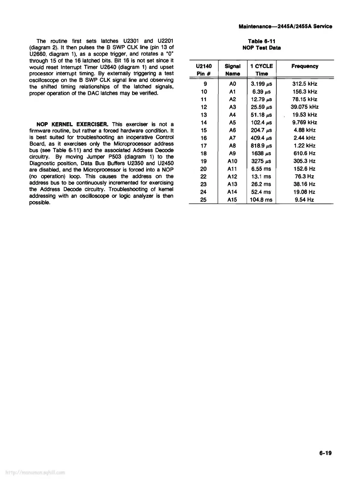
NOP
KERNEL EXERCISER. This exerciser is not a
firmware routine, but rather a forced hardware condition. It
is
best suited for troubleshooting
an
inoperative Control
Board, as it exercises only the Microprocessor address
bus
(see
Table 6-11)
and
the associated Address Decode
circuitry. By moving Jumper P503 (diagram
1)
to
the
Diagnostic position, Data Bus Buffers U2350
and
U2450
are disabled, and the Microprocessor
is
forced into a NOP
(no operation) loop. This causes the address on the
address bus
to
be
continuously incremented for exercising
the Address Decode circuitry. Troubleshooting of kernel
addressing with
an
oscilloscope or logic analyzer
is
then
possible.
U2140
Pin#
9
10
11
12
13
14
15
16
17
18
19
20
22
23
24
25
Maintenance-2445A/2455A Service
Signal
Name
AO
A1
A2
A3
A4
AS
A6
A7
AS
A9
A10
A11
A12
A13
A14
A15
Table
6-11
NOP Test Data
1 CYCLE
Time
3.199
µS
6.39
µS
12.79
µ5
25.59
µS
51.18µ5
102.4
µS
204.7
µS
409.4
µ5
818.9
µS
1638
µS
3275
µS
6.55 ms
13.1
ms
26.2 ms
52.4 ms
104.8
ms
Frequency
312.5 kHz
156.3 kHz
78.15 kHz
39.075 kHz
19.53 kHz
9.769 kHz
4.88
kHz
2.44 kHz
1.22 kHz
610.6 Hz
305.3
Hz
152.6
Hz
76.3 Hz
38.16
Hz
19.08
Hz
9.54 Hz
6-19