Display Format
The Tests
and
Exercisers routines display information
about the routine type and number,
as
well
as
any
test
results, at the bottom of the CRT display. The readout
line
is formatted
as
follows:
OD
TYPE
XV
STATUS
ZZ
LOOP
OD<ABCC>
The information
is
defined
as
follows:
"OD"
is
a two-character option designator identifying
the option that this particular line of diagnostic information
refers to
(see
Options
manual
for details). For the basic
instrument, the
OD
location
is
blank.
"TYPE" refers to routine type:
All
Tests
(ALL),
Test
(TEST),
Exerciser
(EXER),
or Calibration (CAL).
"X"
indicates which bit of the "Option Select Register"
is
set to turn
on
the option called out by "OD"
(see
Options manual for description of Options Select Register).
This bit is zero for the basic instrument.
"Y"
is
the TYPE number of the routine
(see
the "Type
Number" column of Table
6-4).
"ST A TUS" shows the results of the last time a selected
test routine ran: either PASS or FAIL. This space
is
blank
for exerciser
and
calibration routines.
When
the diagnos-
tics
are
called
up
from normal operating mode, the space
will
be
blank until the selected test
is
executed.
"ZZ"
is
a two-digit error code identifying the nature of
the failure
in
a failed test
(see
the "Error Code" column of
Table
6-4).
"LOOP" indicates when a selected test is set to the
LOOP
mode.
"OD<ABCC>"
is the CYCLE mode failure indicator.
CYCLE mode,
when
entered by removing the
NO
CAL/CAL jumper
(P501)
before turning the instrument
on,
causes the instrument to continuously
LOOP
through the
Power
Up
Diagnostic Tests. If a failure occurs, the cycle-
failure data, identifying the first failure encountered,
is
writ-
ten to RAM. Thereafter, at
each
power-up, the Diagnostic
Monitor
is
automatically entered,
and
the failure data
is
displayed. The failure data must
be
cleared from the RAM
location to eliminate the CYCLE mode failure display (see
CYCLE
ERROR
CLEAR Exerciser
03).
The
information
displayed
is
an
abbreviated version of the previous items:
Maintenance-2445A/2455A Service
"OD"
is
a two-character option designator showing
which option failed first while
in
the CYCLE
mode
(the
same codes
as
for "OD" at the start of the readout
line).
"A"
identifies the option-select bit for the failing option
(the same code
as
for "X").
"B"
is
the test Type Number where the failure occurred
(the same codes
as
for "Y").
"CC"
is
the error code for the test (the same codes
as
for "ZZ").
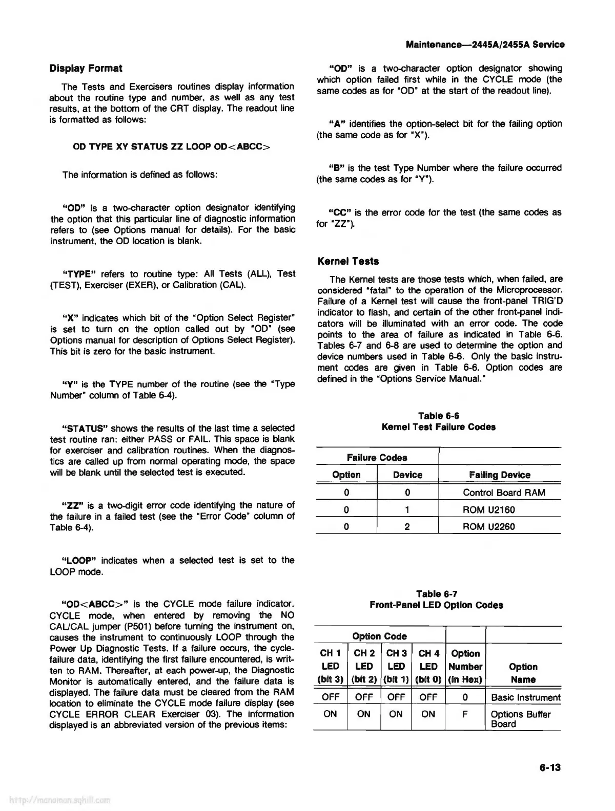
Kernel Tests
The
Kernel
tests are those tests which, when failed, are
considered "fatal" to the operation of the Microprocessor.
Failure of a
Kernel
test will cause the front-panel TRIG'D
indicator to flash,
and
certain of the other front-panel indi-
cators will
be
illuminated with
an
error code.
The
code
points to the
area
of failure as indicated
in
Table 6-6.
Tables
6-
7
and
6-8 are used to determine the option
and
device numbers
used
in
Table 6-6. Only the basic instru-
ment codes
are
given
in
Table 6-6. Option codes
are
defined
in
the "Options Service Manual.·
Table 6-6
Kernel Test Failure Codes
Failure Codes
Option Device
Failing Device
0
0
0
CH
1
LED
(bit 3)
OFF
ON
0 Control Board
RAM
1
ROM
U2160
2
ROM
U2260
Table 6-7
Front-Panel LED Option Codes
Option Code
CH
2
CH3
CH4
Option
LED
LED
LED Number
Option
(bit 2) (bit 1) (bit 0) (in Hex)
Name
OFF
OFF
OFF
0 Basic Instrument
ON ON
ON
F Options Buffer
Board
6-13