1.
Function Generator (60 Hz, 30 kHz and 80 kHz)
2.
Primary Leveled Sine-Wave Generator (50 MHz
and 250 MHz)
3.
Secondary Leveled Sine-Wave Generator
(300 MHz and 500 MHz)
NOTE
To
obtain signal amplitudes less than 1
division, first set the signal for either
4,
5,
or
10
times
the
specified amplitude; then
reduce the amplitude by a factor
of
4,
5,
or
10
by increasing the
VOL
TS/DIV settings
as necessary.
c.
For each combination listed in the table, set the gen-
erator Test Frequency and the oscilloscope TRIGGER
COUPLING as indicated, performing the following steps
to
verify the Triggering levels in each setup.
d.
Set the VOL TS/DIV and the generator output level
to
obtain the test signal amplitude indicated for the particular
combination being tested. When checking channel 1 and
channel 2 500 MHz triggering, also adjust the VOL TS/DIV
VAR for the correct input level.
e.
Set the A SEC/DIV and the X10 MAG
to
obtain a
well-defined display
of
the test signal.
NOTE
Normally, unless trigger sensitivity
is
very
close to the specified limits,
it
is sufficient
to check each
of
the indicated frequency-
coupling combinations listed in the table in
Channel 1 only; checks for Channels
2,
3
and 4
need only be
done
in
DC
COUPLING
(to verify signal path).
f.
CHECK-For
a stably triggered display (unless other-
wise indicated) for each
of
the Test Frequency-TRIGGER
COUPLING combinations listed in Table 4-5. When testing
the 150-MHz 2445A
or
250-MHz 2455A triggering, check
that trigger jitter
is
< 100
ps
(0.2 division at 5 ns/div with
X10
MAG),
with 5 divisions of signal and TRIGGER LEVEL
adjusted for minimum jitter.
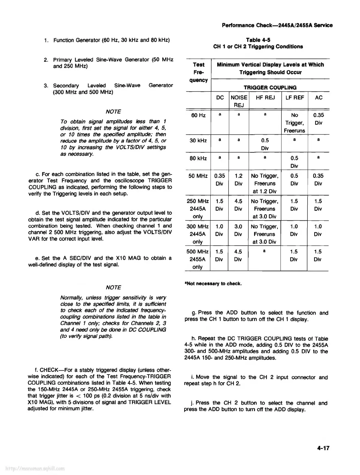
Test
Fre-
quency
60 Hz
30 kHz
80 kHz
50 MHz
250 MHz
2445A
only
300 MHz
2445A
only
500 MHz
2455A
only
Performance
Check-2445A/2455A
Service
Table 4-5
CH
1 or
CH
2 Triggering Conditions
Minimum Vertical Display Levels
at
Which
Triggering Should Occur
TRIGGER COUPLING
DC
NOISE
HF
REJ
LF
REF AC
REJ
a a
a
No 0.35
Trigger,
Div
Freeruns
a
a
0.5
a a
Div
a a
a
0.5
a
Div
0.35 1.2
No Trigger, 0.5 0.35
Div Div
Freeruns
Div Div
at
1.2 Div
1.5
4.5
No
Trigger, 1.5
1.5
Div Div Freeruns Div Div
at
3.0 Div
1.0 3.0 No Trigger, 1.0 1.0
Div Div Freeruns Div Div
at
3.0 Div
1.5
4.5
a
1.5 1.5
Div Div
Div Div
•Not
necessary
to
check.
g.
Press the ADD button
to
select the function and
press the
CH
1 button
to
turn off the
CH
1 display.
h.
Repeat the
DC
TRIGGER COUPLING tests
of
Table
4-5 while
in
the ADD mode, adding 0.5 DIV
to
the 2455A
300- and 500-MHz amplitudes and adding 0.5 DIV to the
2445A 150- and 250-MHz amplitudes.
i.
Move the signal
to
the
CH
2 input connector and
repeat step h for
CH
2.
j. Press the
CH
2 button
to
select the channel and
press the ADD button
to
turn off the ADD display.
4-17