Performance
Check-244SA/24SSA
Service
k.
Repeat the
DC
TRIGGER COUPLING tests of Table
4-5 while
in
CH
2 mode.
I.
If trigger sensitivity is close
to
the specified limits
given
in
steps c through k above, test
all
of the
frequency-coupling combinations given
in
Table 4-5 for
CH
2.
m.
Move the test signal to
CH
3
and
CH
4
in
turn and
repeat parts c through
fusing
Table
4-6.
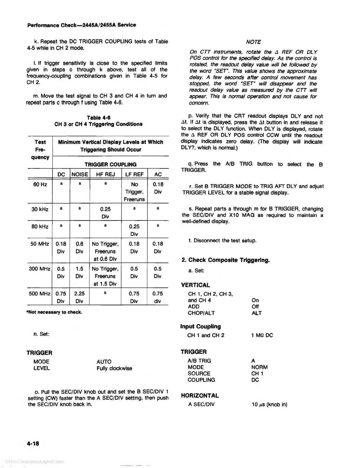
Table 4-6
CH
3 or
CH
4 Triggering Conditions
Test
Minimum Vertical Display Levels
at
Which
Fre-
Triggering Should Occur
quency
TRIGGER COUPLING
DC
NOISE
HF
REJ
LF REF
AC
60
Hz
a a
a
No
0.18
Trigger, Div
Freeruns
30 kHz
a
a
0.25
a
a
Div
80 kHz
a
a
a
0.25
a
Div
50 MHz
0.18
0.6
No
Trigger, 0.18 0.18
Div Div
Freeruns Div
Div
at 0.6 Div
300 MHz 0.5
1.5
No
Trigger, 0.5 0.5
Div
Div Freeruns
Div
Div
at
1.5
Div
500 MHz 0.75 2.25
a
0.75 0.75
Div Div Div div
•Not necessary to check.
n. Set:
TRIGGER
MODE
LEVEL
AUTO
Fully clockwise
o.
Pull
the SEC/DIV knob out and set the 8 SEC/DIV 1
setting (CW) faster than the A SEC/DIV setting, then push
the SEC/DIV knob back
in
.
4-18
NOTE
On CTT instruments, rotate the
L1
REF OR
DL
Y
POS control for the specified delay. As the control is
rotated, the readout delay value will be followed
by
the word "SET".
This
value shows the approximate
delay. A few seconds after control movement has
stopped, the word
"SET" will disappear and
the
readout delay
value
as measured
by
the CTT will
appear.
This
is normal operation and
not
cause for
concern.
p.
Verify that the CRT readout displays DL Y
and
not
.:lt. If .:lt is displayed, press the
at
button
in
and release it
to
select the DL Y function. When DL Y is displayed, rotate
the
.:l
REF
OR
DL Y POS control CCW until the readout
display indicates zero delay. (The display will indicate
DLY?, which is normal.)
q. Press the
NB TRIG button
to
select the B
TRIGGER.
r.
Set 8 TRIGGER MODE
to
TRIG AFT DL Y and adjust
TRIGGER LEVEL for a stable signal display.
s.
Repeat parts a through m for B TRIGGER, changing
the SEC/DIV and
X10 MAG as required
to
maintain a
well-defined display.
t. Disconnect the test setup.
2. Check Composite Triggering.
a.
Set:
VERTICAL
CH
1 ,
CH
2,
CH
3,
and
CH
4
ADD
CHOP/ALT
Input Coupling
CH
1
and
CH
2
TRIGGER
A/8
TRIG
MODE
SOURCE
COUPLING
HORIZONTAL
A SEC/DIV
On
Off
ALT
1 Mll
DC
A
NORM
CH
1
DC
1 O
µS
(knob
in)