Adjustment
Procedure-2445A/2455A
Service
q.
CHECK-Readout
indicates ADJ d (step)
2,
100
µS
(for A Sweep), and 1
µs
(for B Sweep).
r.
ADJUST
-d
REF
OR
DL Y
POS
control to intensify
the 2nd time marker, and ADJUST
-d
control
to
intensify
the 10th time marker. Superimpose the delayed B-Sweep
time markers within 0.2 division.
s.
Press and release the upper TRIGGER COUPLING
switch.
t.
CHECK-Readout
indicates ADJ d (step) 3, 300
µS
(for A Sweep), and 1
µs
(for B Sweep).
u.
ADJUST
-d
REF
OR
DL Y
POS
control
to
intensify
the 4th time marker, and ADJUST
-d
control
to
intensify
the 28th time marker. Superimpose the delayed B-Sweep
time markers within 1.2 divisions.
v.
Press and release the upper TRIGGER COUPLING
switch. If the adjustment
in
step 3 was changed, step 2
will
be recalled; otherwise step 4
will
be initiated.
w.
CHECK-Readout
indicates ADJ d (step)
4,
100
µS
(for A Sweep), and 1 µs (for B Sweep). Set the Time-Mark
Generator for
5-µs time markers.
x. ADJUST
-d
control CCW until no further movement
of
the B-Sweep display occurs. Note the position
of
the
1st time marker, then adjust the d control CW until the
2nd time marker moves
to
the left and aligns with the
position just noted.
NOTE
Movement
of
the
.a
REF control
at
this point will
adversely affect the calibration.
y. Press and release the upper TRIGGER COUPLING
switch. Set the Time-Mark Generator for
10-µ5
time
markers.
z.
CHECK-Readout
indicates X1, X10, HRZ CTR,
(step)
5,
and
10 µs (for A Sweep) and two vertical cursors
appear on the display.
aa.
ADJUST
-X1
Gain (R860) and Hrz Ctr (R801)
to
align the two cursors with the 2nd and 10th vertical grati-
cule lines, then adjust X10
Gain
(R850) for 1 time marker
per division.
5-12
bb. Press and release the upper TRIGGER COUPLING
switch. Set the Time-Mark Generator for 10-ms time
markers.
cc.
CHECK-Readout
indicates ADJ d (step)
6,
10 ms
(for A Sweep), and 100
µs (for B Sweep).
dd. ADJUST
-d
REF
OR
DL Y POS control
to
intensify
the 2nd time marker, and ADJUST
-d
control
to
intensify
the 10th time marker. Superimpose the delayed B-Sweep
time markers within 0.2 division.
ee.
Press and release the upper TRIGGER COUPLING
switch. Set the Time-Mark Generator for
1-µs time
markers.
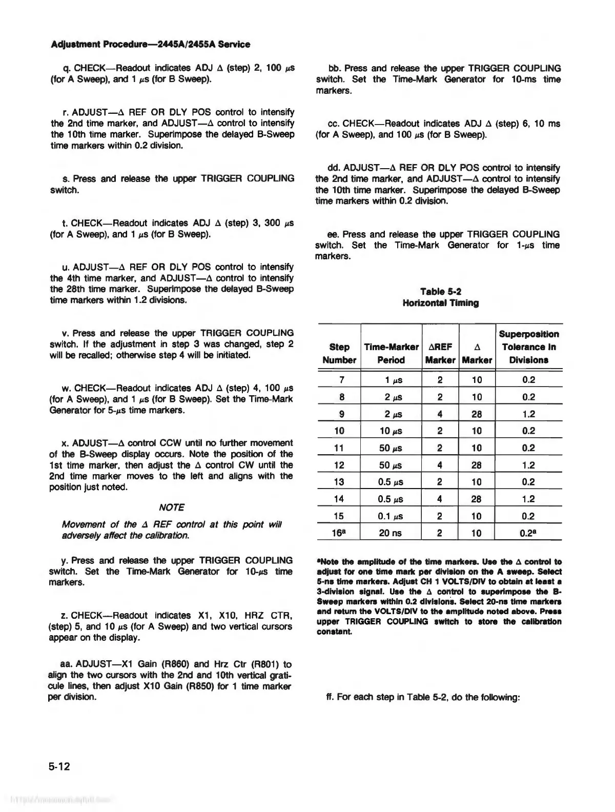
Step
Number
7
8
9
10
11
12
13
14
15
16
8
Table 5-2
Horizontal Timing
Time-Marker
dREF
d
Period Marker Marker
1
µS
2
10
2
µS
2
10
2
µS
4 28
10
µS
2
10
50
µS
2 10
50
µ5
4
28
0.5
µS
2 10
0.5
µS
4 28
0.1
µS
2 10
20
ns
2 10
Superposition
Tolerance In
Divisions
0.2
0.2
1.2
0.2
0.2
1.2
0.2
1.2
0.2
0.2
8
•Note the amplitude
of
the time markers. Uee the
~
control to
adjuet for one time mark per dlvlelon on the A eweep. Select
5-n•
time markers. Adjuet CH 1
VOL
TS/DIV to obtain at
leHt
a
3-dlvlelon eignal.
U.e
the
~
control
to
euperlmpoee the
8--
Sweep markere within 0.2 dlvlelone. Select 20-ne time markers
and retum
the VOL TS/DIV
to
the amplitude noted above.
Pre••
upper
TRIGGER
COUPLING
ewltch
to
etore the calibration
conetant.
ff. For each step
in
Table 5-2,
do
the following: