1.
Adjust the A
REF
OR
DL Y POS
and
A controls,
as necessary, to intensify the indicated time
marks on the A Sweep and superimpose the
displayed B-Sweep markers within the listed
limits.
2.
Press
and
release the upper TRIGGER COU-
PLING switch.
NOTE
If
the
L1
control ls adjusted
at
step
9,
12
or
14,
the previous step will
be
repeated.
gg. Set the TRACE SEP fully
CW.
hh.
Connect the Time Mark Generator output
to
CH
1
of
both the IUT (instrument under test) and the bench
scope via a BNC
·r
and
two 50-n BNC cables. Connect
B GATE OUT
of
I UT
to
CH
2
of
bench scope
via
a
50-11
BNC cable.
ii. Set bench scope to
view
CH
1,
TRIGGER SOURCE
to
CH
2,
and
CH
1 and
CH
2 input coupling
to
50
n.
Adjustment Procedure-2445A/2455A Service
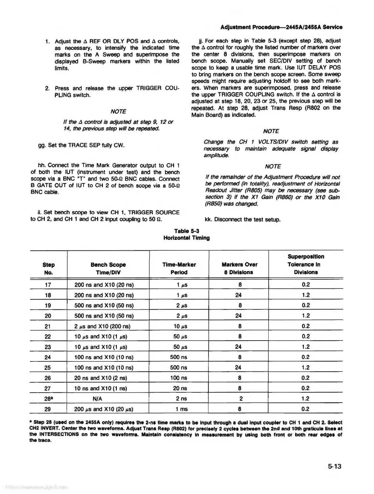
jj. For each step
in
Table 5-3 (except step
28),
adjust
the
A control for roughly the listed number
of
markers over
the center 8 divisions, then superimpose markers on
bench scope. Manually set SEC/DIV setting of bench
scope to keep a usable time mark. Use IUT DELAY
POS
to
bring markers on the bench scope screen. Some sweep
speeds might require adjusting holdoff
to
see both mark-
ers. When markers are superimposed, press
and
release
the upper TRIGGER COUPLING switch. If the
A control is
adjusted at step 18, 20, 23 or 25, the previous step will be
repeated.
At
step 28, adjust Trans Resp (R802 on the
Main Board) as indicated.
NOTE
Change the CH 1
VOL
TS/DIV switch setting as
necessary to maintain adequate signal display
amplitude.
NOTE
If
the remainder
of
the Adjustment Procedure will
not
be
performed (in totality), readjustment
of
Horizontal
Readout Jitter (R805) may
be
necessary (see sub-
section 3)
if
the
X1
Gain (R860)
or
the X10 Gain
(R850) was changed.
kk. Disconnect the test setup.
Table 5-3
Horizontal Timing
Superposition
Step
Bench Scope
Time-Marker
Markers Over Tolerance
In
No.
Time/DIV
Period
8 Divisions Divisions
17
200 ns
and
X10 (20 ns)
1
µ.S
8 0.2
18
200 ns
and
X10 (20 ns)
1
µ.S
24
1.2
19
500 ns
and
X10 (50 ns) 2
µ.S
8
0.2
20
500 ns
and
X10 (50 ns)
2
µ.S
24
1.2
21
2
µ.s
and
X10 (200 ns)
10
µ.S
8 0.2
22
10 µ.Sand X10
(1
µ.S)
50
µS
8
0.2
23
10
µ.Sand X10
(1
µ.S)
50
µS
24 1.2
24
100 ns
and
X10 (10 ns) 500 ns 8
0.2
25
100 ns
and
X10 (10 ns) 500 ns
24
1.2
26
20 ns
and
X10
(2
ns)
100 ns 8 0.2
27
10 ns
and
X10
(1
ns)
20
ns 8
0.2
28
8
N/A
2 ns 2
1.2
29
200 µ.Sand X10 (20
µ.S)
1 ms 8 0.2
• Step
28
(used on the 2455A only) requires the
2-n•
time marks to
be
input through a dual Input coupler to
CH
1 and
CH
2.
Select
CH2
INVERT. Center the two waveforms. Adjust
Tran•
Resp (R802) for precisely 2 cycles between the 2nd and 10th graticule
line•
at
the INTERSECTIONS on the two waveforms. Maintain consistency in measurement by using both front or both rear edges
of
the traca.
5-13