Adjustment
Procedure-2445A/2455A
Service
CAL
02-VERTICAL
2.
Check/Adjust Vertical Preamplifier Gain, Gain
(R638), and Vertical Centering (R639).
NOTE
If
the previous step (CAL
01)
was
not
performed, the
adjustments in this subsection should only be per-
formed
if
those constants that would have been set
in
CAL
01
are known to be correct.
a.
Set the front-panel INTENSITY control at midrange.
b.
Scroll
to
CAL
02.
c.
Press
and
release
the upper TRIGGER COUPLING
switch.
The
instrument will automatically increment
through steps 1
00
to 110.
d.
CHECK-Readout
indicates
CH
1 VAR,
CH2
POS,
(step) 111, and 500
mV.
NOTE
The
readout prompts the operator
by
showing the
controls to be moved (upper left comer and upper
center), the autocal step number (upper right comer),
the amplitude
of
signal to be applied to either the
CH 1
or
CH 2 connectors (lower left comer), and any
other scope function that is enabled. An example
(from step d above) is:
CH1
VAR
CH2
POS
111
500mV
e.
Connect a 0.5-V, standard-amplitude signal from the
Calibration Generator
to
the
CH
1
OR
X input connector
via a
50-n
BNC
cable.
f.
Use the
CH
2 POSITION control
to
vertically position
the trace to within 1 division of the center graticule line.
g. ADJUST
-CH
1 POSITION
and
VOL TS/DIV VAR
controls to obtain a 1 0-division horizontal signal. Press
and
release the upper TRIGGER COUPLING switch.
5-14
NOTE
When
step
111
is performed, step 112 is also
automatically
done.
No indication
of
step 112 will be
shown unless a LIMIT error is indicated.
NOTE
In the following steps,
if
the ·LIMIT" message
appears,
it
probably indicates that the
TRIGGER
COUPLING (step) switch was moved before the
required signal was applied. Press and release the
lower
TRIGGER
COUPLING switch, verify that the
correct signal is applied, then press and release the
upper
TRIGGER
COUPLING switch.
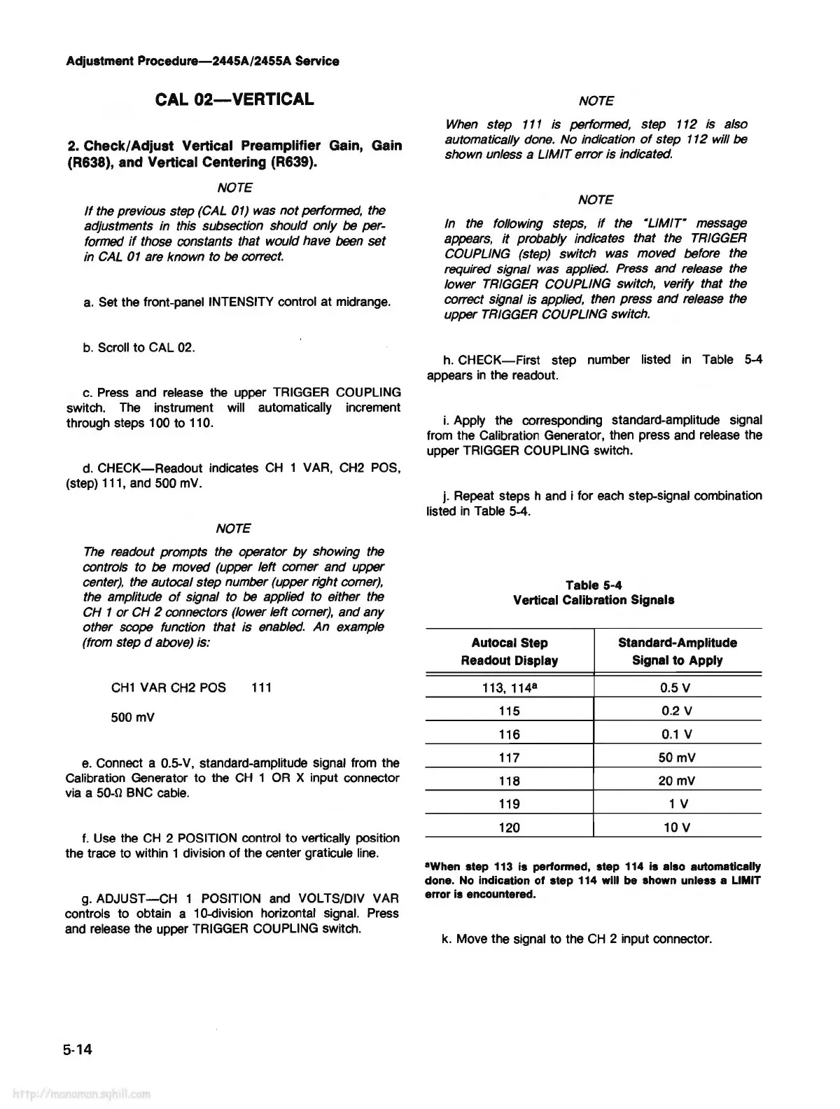
h.
CHECK-First
step number listed
in
Table 5-4
appears
in
the readout.
i.
Apply the corresponding standard-amplitude signal
from the Calibration Generator, then press and release the
upper TRIGGER COUPLING switch.
j. Repeat steps h and i for
each
step-signal combination
listed
in
Table 5-4.
Table 5-4
Vertical Calibration Signals
Autocal Step
Standard-Amplitude
Readout Display Signal to Apply
113, 114
8
0.5 V
115
0.2 V
116
0.1
V
117
50mV
118
20mV
119
1 V
120 10 V
•when
step 113 is performed, step 114 is also automatically
done. No indication
of
step 114 will be shown unless a LIMIT
error
is encountered.
k.
Move the signal to the
CH
2 input connector.