3. Check Data Hold Time.
a.
For
each
test setup described
in
Table 4-12: Vary
the
pulse
duration of
pulse
generator # 2 until the first
edge of the channel 2 signal falls about 10
ns
after the
trigger
edge
of the channel 1 signal.
2.
CHECK-A
stable signal is displayed
on
chan-
nel
3.
3.
Vary the pulse duration of
pulse
generator #
2,
moving the first
edge
of the channel 2 signal to
the left until
channel
3
no
longer displays a
stable signal.
4.
Push
the
at
button.
5.
Turn
the
a
REF
OR
DL
Y
POS
control to align
the delta reference cursor with the first
edge
of
the channel 2 signal.
6.
Turn the a control to align
the
delta cursor with
the first
edge
of the channel 1 signal.
7.
CHECK-Reading
is>
4
ns.
8.
Push
the
at
button.
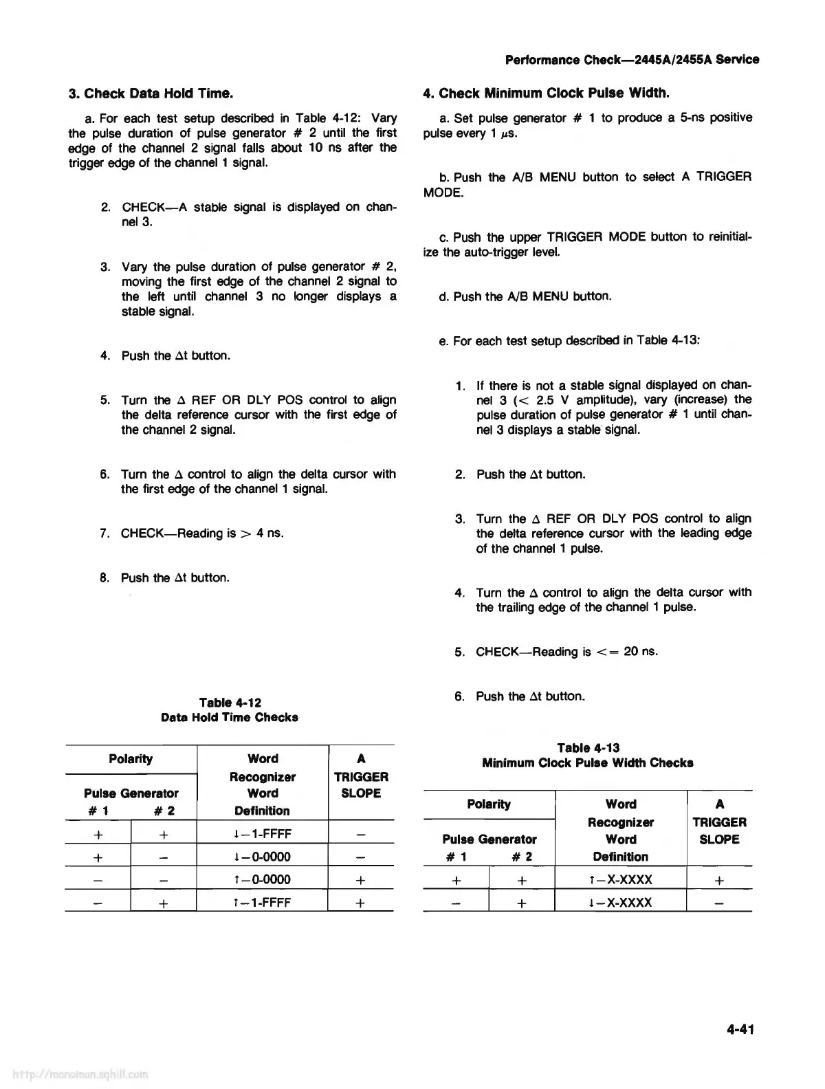
Table 4-12
Data Hold Time Checks
Polarity
Word
A
Recognizer TRIGGER
Pulse Generator
Word SLOPE
# 1
#2
Definition
+ +
!-1-FFFF
-
+
-
!-0-0000
-
-
-
l-0-0000
+
-
+
l-1-FFFF
+
Performance
Check-2445A/2455A
Service
4. Check Minimum Clock Pulse Width.
a.
Set pulse generator # 1 to produce a 5-ns positive
pulse every 1
µS.
b.
Push
the NB
MENU
button to select A
TRIGGER
MODE.
c.
Push
the upper TRIGGER
MODE
button to reinitial-
ize
the auto-trigger
level.
d.
Push
the NB
MENU
button.
e.
For
each
test setup described
in
Table 4-13:
1.
If there
is
not a stable signal displayed
on
chan-
nel
3 ( < 2.5 V amplitude), vary (increase) the
pulse duration of pulse generator
# 1 until chan-
nel
3 displays a stable signal.
2.
Push
the
at
button.
3.
Turn the a
REF
OR
DL
Y
POS
control to align
the delta reference cursor with the leading
edge
of the
channel
1
pulse.
4.
Turn the a control to align
the
delta cursor with
the trailing
edge
of
the channel 1 pulse.
5.
CHECK-Reading
is
< = 20
ns.
6.
Push
the
at
button.
Table 4-13
Minimum Clock
Pulse Width Checks
Polarity Word
A
Recognizer
TRIGGER
Pulse Generator
Word SLOPE
#1
#2
Definition
+ +
l-X-XXXX
+
-
+
!-X-XXXX
-
4-41