I.
CHECK-Readout
indicates CONNECT SIGNAL
TO
CH
2,
(step) 121,500
mV,
500
mV,
and
BWL.
m.
Set the Calibration Generator for a 500-mV
standard-amplitude signal, then press and release the
upper
TRIGGER
COUPLING switch.
NOTE
When
step
121
is performed, step 122 is also
automatically
done.
No
indication
of
step 122 will
be
shown unless a LIMIT
e"or
is indicated.
n.
CHECK-First
step number listed
in
Table 5-5
appears
in
the readout.
o.
Apply the corresponding standard-amplitude signal,
then press
and
release the upper TRIGGER COUPLING
switch.
p.
Repeat steps n
and
o for
each
step-signal combina-
tion listed
in
Table 5-5.
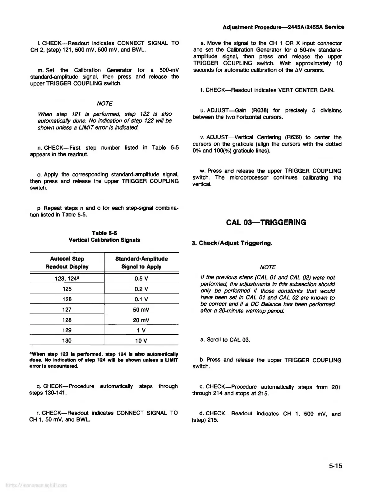
Table 5-5
Vertical Calibration Signals
Autocal Step Standard-Amplitude
Readout Display Signal to Apply
123, 124
8
0.5 V
125 0.2 V
126
0.1
V
127
50mV
128
20mV
129
1 V
130
10 V
•when
step 123 Is performed, step 124 is also automatically
done. No indication of step 124 will be shown unless a LIMIT
error
is
encountered.
q.
CHECK-Procedure automatically steps through
steps 130-141.
r.
CHECK-Readout indicates CONNECT SIGNAL
TO
CH
1,
50
mV,
and
BWL.
Adjustment
Procedure-2445A/2455A
Service
s.
Move the signal to the
CH
1
OR
X input connector
and
set the Calibration Generator for a 50-mv standard-
amplitude signal, then press
and
release the upper
TRIGGER
COUPLING switch.
Wait
approximately 10
seconds for automatic calibration
of
the
~
V cursors.
t. CHECK-Readout indicates VERT CENTER
GAIN.
u.
ADJUST
-Gain
(R638) for precisely 5 divisions
between the two horizontal cursors.
v.
ADJUST
-Vertical
Centering (R639) to center the
cursors
on
the graticule (align the cursors with the dotted
0%
and
100(%) graticule lines).
w.
Press and release the upper TRIGGER COUPLING
switch.
The
microprocessor continues calibrating the
vertical.
CAL 03-TRIGGERING
3.
Check/
Adjust
Triggering.
NOTE
If
the
previous steps (CAL
01
and CAL 02) were
not
performed,
the
adjustments
in
this subsection should
only
be
performed
if
those constants that would
have been set in CAL
01
and CAL 02 are known to
be
co"ect
and
if
a DC Balance has been performed
after a 20-minute warmup period.
a.
Scroll to CAL 03.
b.
Press
and release the upper TRIGGER COUPLING
switch.
c.
CHECK-Procedure automatically steps from
201
through 214
and
stops at 215.
d.
CHECK-Readout indicates
CH
1,
500
mV,
and
(step)
215.
5-15