Performance
Check-2445A/2455A
Service
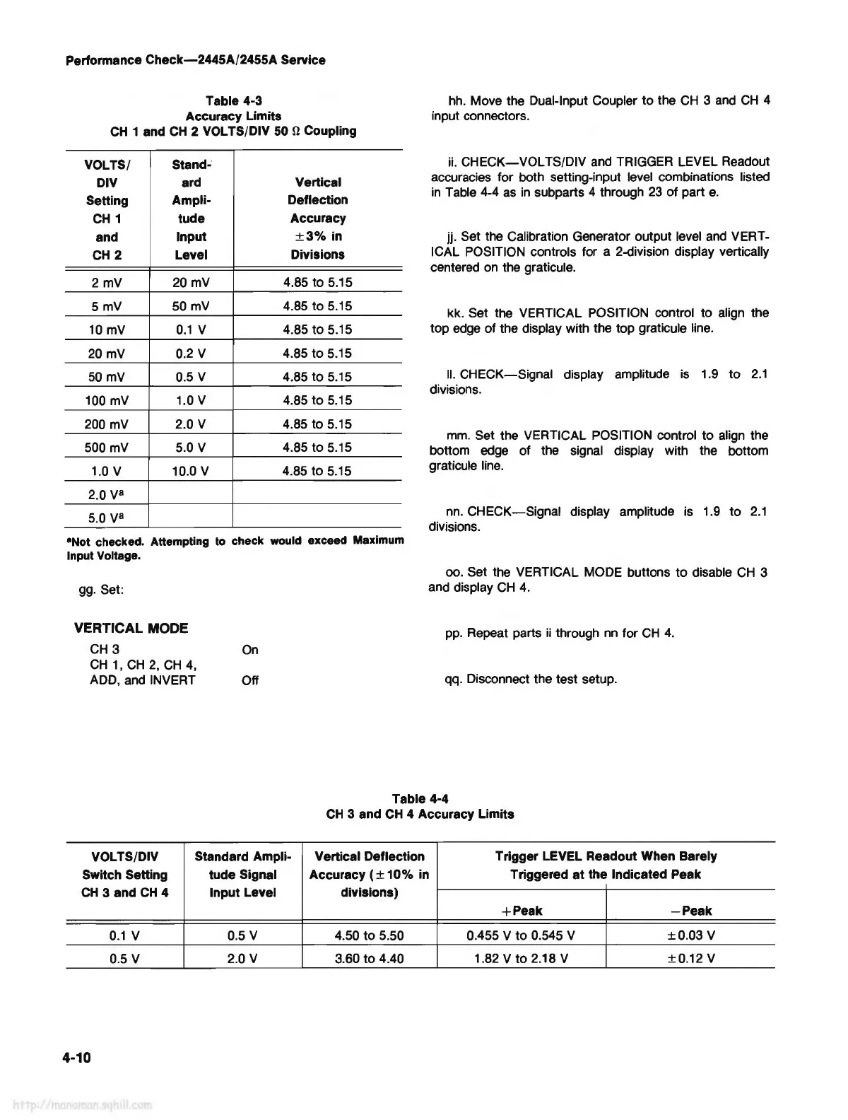
Table 4-3
Accuracy Limits
CH
1 and
CH
2 VOL TS/DIV 50 n Coupling
VOLTS/
Stand-
DIV
ard Vertical
Setting
Ampli- Deflection
CH
1
tude
Accuracy
and
Input
±3%
in
CH
2
Level
Divisions
2
mV
20
mV
4.85 to 5.15
5mV
50
mV
4.85 to 5.15
10
mV
0.1
V 4.85 to 5.15
20
mV
0.2 V
4.85 to 5.15
50
mv
0.5 V
4.85 to 5.15
100
mV
1.0 V
4.85 to 5.15
200
mV
2.0 V
4.85 to 5.15
500mV
5.0 V 4.85 to 5.15
1.0 V 10.0 V
4.85 to 5.15
2.0 V
8
5.0
V
8
•Not checked. Attempting
to
check
would
exceed Maximum
Input
Voltage.
gg.
Set:
VERTICAL MODE
CH
3
CH
1,
CH
2,
CH
4,
ADD,
and
INVERT
On
Off
hh.
Move the Dual-Input Coupler to the
CH
3
and
CH
4
input connectors.
ii.
CHECK-VOL
TS/DIV
and
TRIGGER LEVEL Readout
accuracies for both setting-input level combinations listed
in
Table 4-4
as
in
subparts 4 through
23
of part
e.
jj. Set the Calibration Generator output level
and
VERT-
ICAL POSITION controls for a 2-division display vertically
centered
on
the graticule.
kk. Set the VERTICAL POSITION control to align the
top
edge
of the display with the top graticule
line.
II.
CHECK-Signal display amplitude
is
1.9 to
2.1
divisions.
mm.
Set the VERTICAL POSITION control to align the
bottom edge of the signal display with the bottom
graticule
line.
nn.
CHECK-Signal
display amplitude is 1.9 to
2.1
divisions.
oo. Set the VERTICAL MODE buttons to disable
CH
3
and display
CH
4.
pp.
Repeat parts
ii
through
nn
for
CH
4.
qq. Disconnect the test setup.
Table 4-4
CH
3 and
CH
4 Accuracy Limits
VOLTS/DIV
Standard Ampli- Vertical Deflection
Trigger LEVEL Readout When Barely
Switch Setting tude Signal Accuracy (
±
10%
in
Triggered
at
the Indicated Peak
CH
3 and
CH
4
Input Level divisions)
+Peak
-Peak
0.1
V 0.5 V 4.50 to 5.50 0.455 V to 0.545 V
±0.03
V
0.5 V 2.0 V 3.60 to 4.40
1.82 V to 2.18 V ±0.12 V
4-10