I.
Set:
Delta
TRACK/INDEP
HORIZONTAL
A SEC/DIV
B SEC/DIV
X10 MAG
TRACK
100
ns
1 0
ns
(knob out)
On
m.
Select 0.1-µs time markers from the Time-Mark
Generator.
n.
Adjust the
~
and
~
REF
OR
DL Y
POS
controls for a
~t
readout display of 800.0
ns.
o.
Adjust the Horizontal POSITION control to align the
leading edge of the 2nd time marker
on
the A sweep with
the
2nd
vertical graticule
line.
p.
Rotate the TRACE
SEP
control CCW to separate
the traces.
q.
Adjust the
~
REF
OR
DL Y
POS
control to intensify
the
2nd
and
10th time markers (of the A sweep)
and
display the leading edges of the displayed B-sweep time
markers
in
the center area of the graticule.
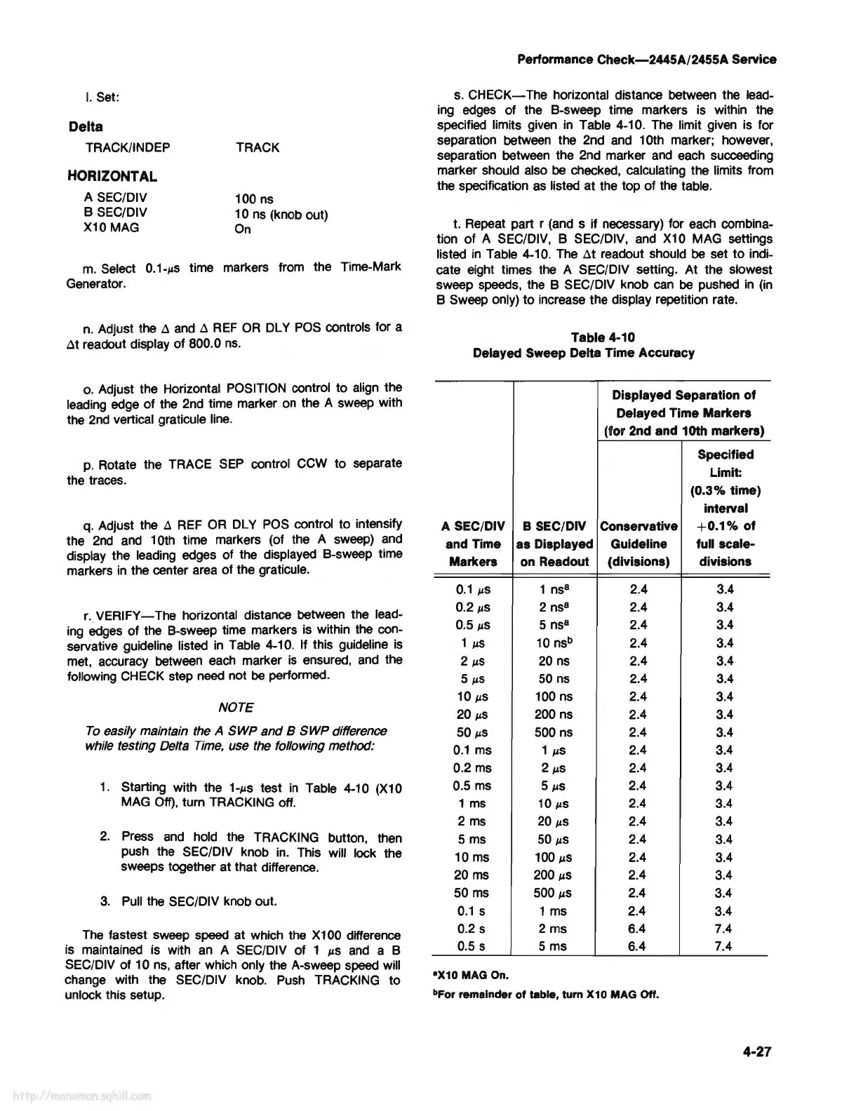
r.
VERIFY-
The
horizontal distance between the lead-
ing
edges of the B-sweep time markers
is
within the con-
servative guideline listed
in
Table 4-10. If this guideline
is
met, accuracy between
each
marker
is
ensured,
and
the
following
CHECK
step
need
not
be
performed.
NOTE
To
easily maintain the A SWP
and
B
SWP
difference
while testing Delta
Time,
use the following method:
1 . Starting with the
1-µs
test
in
Table 4-10
(X
10
MAG
Off),
turn TRACKING off.
2.
Press
and
hold the TRACKING button, then
push the SEC/DIV knob
in.
This will lock the
sweeps together at that difference.
3.
Pull
the SEC/DIV knob out.
The
fastest sweep speed at which the X100 difference
is
maintained is with
an
A SEC/DIV of 1
µs
and
a B
SEC/DIV of 10
ns,
after which only the A-sweep speed will
change with the SEC/DIV knob.
Push
TRACKING to
unlock this setup.
Performance
Check-2445A/2455A
Service
s.
CHECK-
The
horizontal distance between the lead-
ing
edges
of the B-sweep time markers is within the
specified limits given
in
Table 4-10.
The
limit given is for
separation between the 2nd
and
10th marker; however,
separation between the 2nd marker
and
each succeeding
marker should also
be
checked, calculating the limits from
the specification
as
listed at the top of the table.
t. Repeat part r (and s if necessary) for each combina-
tion of A SEC/DIV, B SEC/DIV,
and
X10
MAG settings
listed
in
Table 4-10.
The
~t
readout should
be
set
to
indi-
cate eight times the A SEC/DIV setting. At the slowest
sweep speeds, the B SEC/DIV knob
can
be
pushed
in
(in
B Sweep only) to increase the display repetition rate.
Table 4-10
Delayed Sweep Delta Time Accuracy
Displayed Separation of
Delayed Time Markers
(for 2nd and 10th markers)
Specified
Limit:
(0.3% time)
interval
A SEC/DIV B SEC/DIV Conservative
+0.1%
of
and Time as Displayed Guideline
full scale-
Markers
on
Readout
(divisions) divisions
0.1
µS
1
ns
8
2.4 3.4
0.2
µS
2
ns
8
2.4 3.4
0.5
µS
5
ns
8
2.4 3.4
1
µS
10
nsb
2.4 3.4
2
µS
20
ns
2.4 3.4
5
µS
50
ns
2.4 3.4
10
µS
100
ns
2.4 3.4
20
µS
200
ns
2.4 3.4
50
µS
500
ns
2.4 3.4
0.1
ms
1
µS
2.4 3.4
0.2
ms
2
µS
2.4 3.4
0.5
ms
5
µS
2.4 3.4
1
ms
10
µS
2.4 3.4
2
ms
20
µS
2.4 3.4
5
ms
50
µS
2.4
3.4
10
ms
100
µS
2.4 3.4
20
ms
200
µS
2.4
3.4
50
ms
500
µS
2.4 3.4
0.1
s
1
ms
2.4
3.4
0.2 s 2 ms 6.4 7.4
0.5 s
5 ms 6.4 7.4
•x10
MAG On.
bFor remainder
of
table, turn X10
MAG
Off.
4-27