Speclflcation-2445A/2455A Service
Table
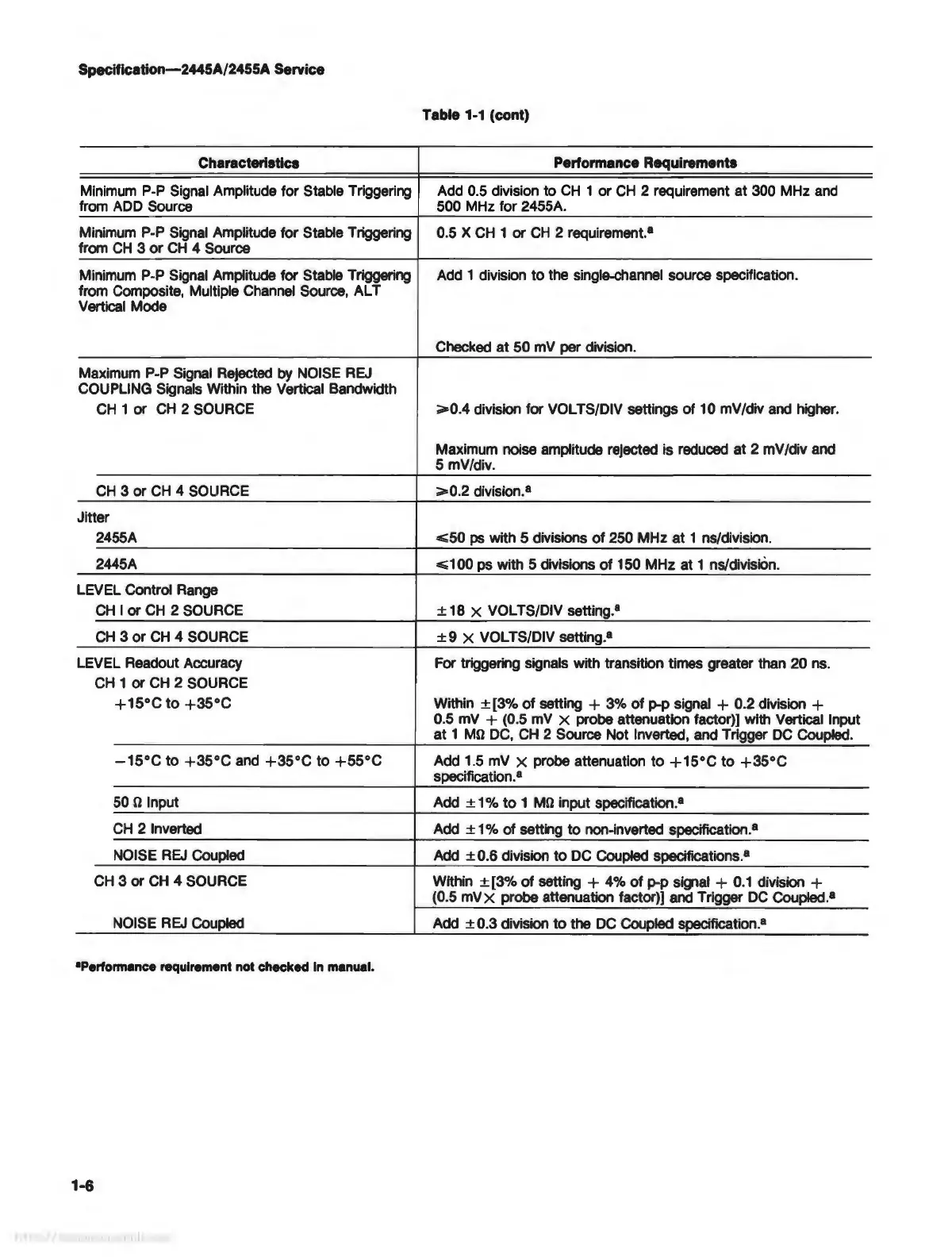
1-1 (cont)
Characteristics
Performance Requirements
Minimum P-P Signal Amplitude for Stable Triggering
Add 0.5 division
to
CH
1
or
CH
2 requirement at 300 MHz and
from ADD Source 500 MHz for 2455A.
Minimum P-P Signal Amplitude for Stable Triggering 0.5 X
CH
1
or
CH
2 requirement.
8
from
CH
3
or
CH
4 Source
Minimum P-P Signal Amplitude for Stable Triggering
Add 1 division
to
the single-channel source specification.
from Composite, Multiple Channel Source, ALT
Vertical Mode
Checked at
50
mV per division.
Maximum P-P Signal Rejected by NOISE REJ
COUPLING Signals Within the Vertical Bandwidth
CH
1
or
CH
2 SOURCE
>=0.4
division for VOL TS/DIV settings of 10 mV /div and higher.
Maximum noise amplitude rejected is reduced at 2 mV /div and
5 mV/div.
CH
3
or
CH
4 SOURCE
>=0.2
division.•
Jitter
2455A
<=50
ps with 5 divisions
of
250 MHz
at
1 ns/division.
2445A
<=100
ps with 5 divisions
of
150 MHz at 1 ns/division.
LEVEL Control Range
CH
I or
CH
2 SOURCE
± 18 X
VOL
TS/DIV setting. (a)
CH
3
or
CH
4 SOURCE ± 9 X
VOL
TS/DIV setting.•
LEVEL Readout Accuracy
For triggering signals with transition times greater than 20 ns.
CH
1
or
CH
2 SOURCE
+15°C
to
+35°C
Within ± [3%
of
setting + 3%
of
p-p signal + 0.2 division +
0.5 mV + (0.5 mV
x probe attenuation factor)] with Vertical Input
at
1
þÿM©
DC,
CH
2 Source Not Inverted, and Trigger
DC
Coupled.
-15°C
to
+35°C
and
+35°C
to
+55°C
Add 1.5 mV X probe attenuation
to
+15°C
to
+35°C
specification.
8
50 þÿ© Input
Add
± 1 %
to
1
þÿM©
input specification.•
CH
2 Inverted
Add
± 1 % of setting
to
non-inverted specification.•
NOISE
REJ
Coupled
Add
± 0.6 division
to
DC Coupled specifications.
8
CH 3 or
CH
4 SOURCE
Within
± [3%
of
setting + 4%
of
p-p
signal
+
0.1
division +
(0.5 mV
x probe attenuation factor)] and Trigger
DC
Coupled. (a)
NOISE REJ Coupled
Add
± 0.3 division
to
the DC Coupled specification.•
•Performance
requirement
not
checked
In
manual.
1-6