Malntenance-2445A/2455A Service
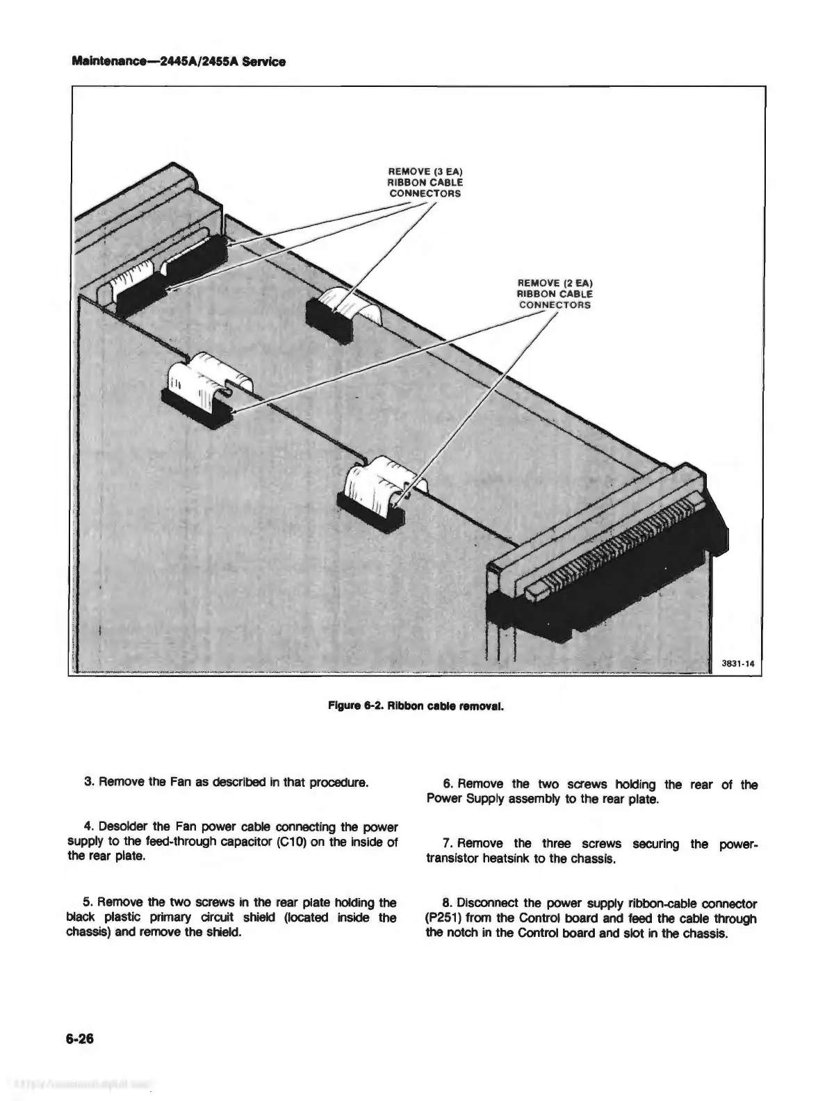
Figure 6-2. Ribbon cable removal.
3. Remove the
Fan
as
described
in
that procedure.
4.
Desolder the
Fan
power cable connecting the power
supply to the feed-through capacitor
(C10)
on
the inside of
the rear plate.
5.
Remove
the two screws
in
the rear plate holding the
black plastic primary circuit shield (located inside the
chassis) and remove the shield.
6-26
6.
Remove the two screws holding the rear of the
Power Supply assembly to the rear plate.
7.
Remove the three screws securing the power-
transistor heatsink to the chassis.
8.
Disconnect the power supply ribbon-cable connector
(P251)
from the Control board
and
feed
the cable through
the notch
in
the Control board
and
slot
in
the chassis.