Maintenance-2445A/2455A Service
~-~
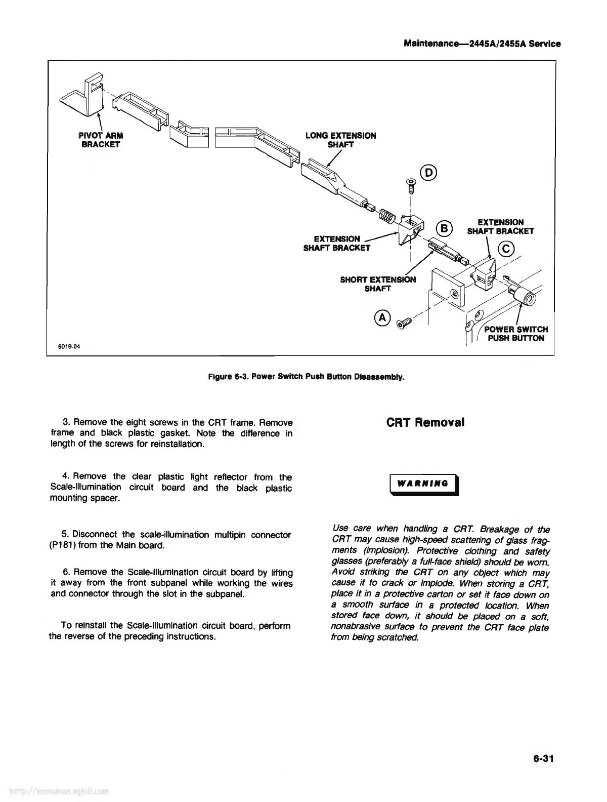
PIVOT ARM
~
~
LONG EXTENSION
BRACKET
"-._I:J
~
SHAFT
6019-04
Figure 6-3. Power Switch Push Button Disassembly.
3.
Remove
the eight screws
in
the CRT
frame.
Remove
frame and black plastic gasket. Note the difference
in
length of the screws for reinstallation.
4.
Remove the clear plastic light reflector from the
Scale-Illumination circuit board
and
the black plastic
mounting spacer.
5.
Disconnect the scale-illumination multipin connector
(P181) from the Main board.
6.
Remove
the Scale-Illumination circuit board by lifting
it away from the front subpanel while working the wires
and
connector through the slot
in
the subpanel.
To reinstall the Scale-Illumination circuit board, perform
the reverse of the preceding instructions.
CRT Removal
WARlfflfQ
I
Use
care
when
handling a
CRT.
Breakage
of
the
CRT may cause high-speed scatten'ng
of
glass frag-
ments (implosion). Protective clothing and safety
glasses (preferably a full-face shield) should
be
wom.
Avoid striking the CRT on any object
which
may
cause
it
to crack
or
implode.
When
storing a
CRT,
place
it
in
a protective carton
or
set
it
face
down on
a smooth surface in a protected location.
When
stored
face
down,
it
should be placed on a soft,
nonabrasive surface to prevent
the
CRT
face
plate
from being scratched.
6-31