Theory of Operation-2445A/2455A Service
with
the
output of
DAC
U2101.
The
processor changes
the
DAC
output until it most closely matches the output
voltage of the pot, then stores the digital
value
of the
"match".
See
the
"Pot Scanning" description
in
the "Ana-
log
Control" discussion for further information
on
the read-
ing
of pot
values.
Like
the switch matrix scanning, the Front-Panel pot
scanning routine
is
performed every 16
ms.
When
entered,
the routine reads the settings of the "last-moved" pot
and
one
·unmoved" pot.
Each
succeeding
scan
continues to
read
the
last-moved pot, but a
new
unmoved pot
is
read.
In
this way,
each
pot
is
monitored, but most of
the
scan
time
is
devoted to the pot that
is
most likely to still be
moving
(needing
continuous updating).
ROW
0
FROM
DATA
LATCHES
U2301
ROW
1
AND
U2201
As the initial pot settings
are
determined, a digital
representation of
each
value
is
stored
in
memory.
The
pro-
cessor
then
checks
each
pot against its last-known value
to determine if a pot has moved. If a pot
is
detected
as
moving, the processor executes a routine that converts
the movement (displacement from last-set
value)
into a
corresponding control voltage.
When
producing the actual analog control
levels,
the
processor
can
manipulate the digital values
read
for the
various pots before sending
the
output data to the
DAC.
This allows many of the oscilloscope parameters to vary
in
an
enhanced
fashion.
The
pot data is manipulated
by
the
processor
in
a manner that produces
such
features
as
variable resolution, continuous rotation, fine-resolution
backlash,
and
electrically detented controls.
-,
COL
TO
DATA
COL
1
SELECTOR
U2410
ROW
9
SWITCH
MATRIX
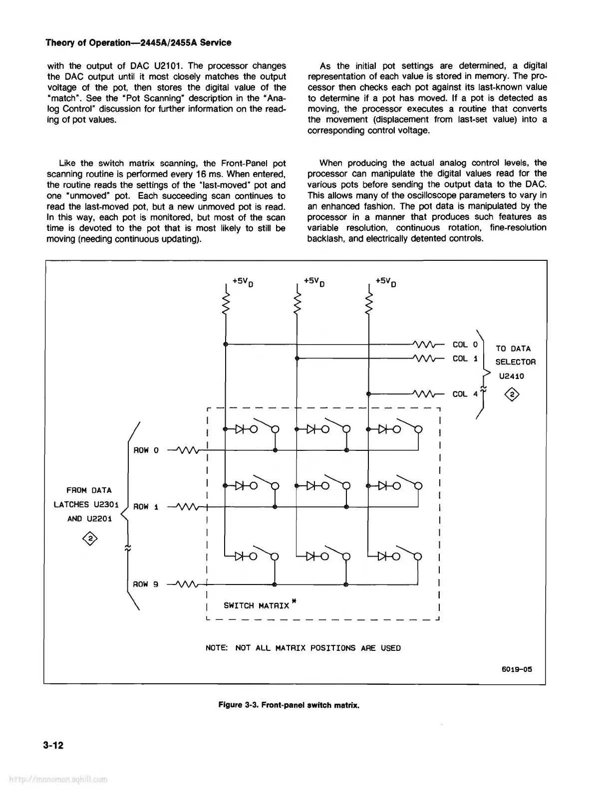
NOTE:
NOT
ALL
MATRIX
POSITIONS
ARE
USED
6019-05
Figure 3-3. Front-panel switch matrix.
3-12