Analog Board
+70V +15V +5V
F
-15V -70V
FFF FF
Output Stage
-1200V -42V +42V +1200V
O
High Voltage
Power
Constant Frequency
Low Noise Floating
Switching Supply
Switching Power
Supply
+12Vd
D
Line
Neutral
+12Vd
D
+5Vd
Digital Circuits
AC1
AC2
Power supply
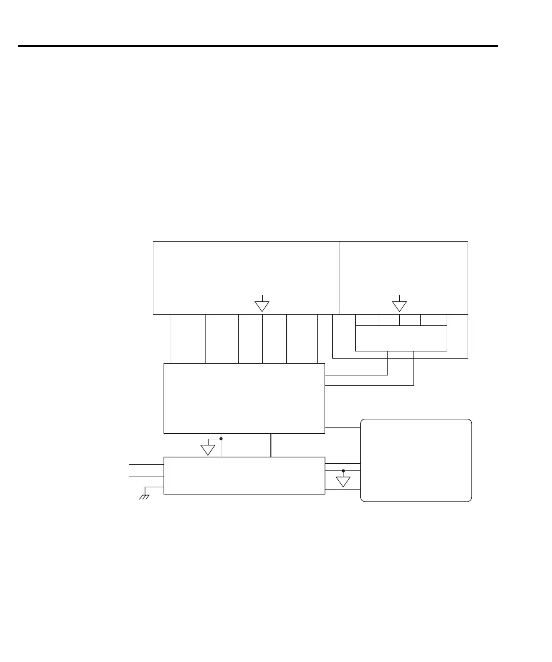
Figure 4-3
shows a block diagram of the Model 2410 power delivery system.
The offline flyback switching power supply provides all power for the instrument while
providing universal inputs for the 110/120V line. The digital board runs directly from the
switcher, including the +12VD supply to program the flash ROM.
A constant-frequency switching supply runs off the +12VD supplies and generates all the
floating supply voltages for the analog board: +5V, ±15V, and ±70VF. An AC output (low
voltage) supplies the analog board with the power it uses to derive the output stage supply
voltages, ±42V and ±1200V.
4-8 Troubleshooting
Figure 4-3
Power supply
block diagram
2410-902-01.book Page 8 Monday, November 7, 2005 2:49 PM