20
To make the front panel BNC input connectors accessible to other equipĆ
ment at the rear of the equipment rack, use the following procedure.
1. Install a BNC connector into the button hole. See Figure 14 on page 18.
a. Remove one of the button plugs from the rightĆfront frame.
b. Open one of the bags containing a BNC connector and the necesĆ
sary mounting hardware.
c. Place the rubber washer on the threaded end of the BNC connector
and insert the connector through the button hole.
d. Secure the BNC connector in place using the lock washer and nut.
e. Use a %@8Ćinch wrench to tighten the nut.
f. Repeat this for each BNC connector you wish to install.
2. Connect a BNC 50 W cable.
a. Connect one end of a BNC cable to the rear of the BNC connector.
b. Ensure that the nylon channel grommets are properly installed into
the channels in the rear support. See Figure 15 on page 19.
c. Feed the other end of the BNC cable through the grommet hole in
the rear support. After you install the rackmounted instrument in the
next section, remember to connect the cable to the desired connecĆ
tor (see on page 34).
3. Place the appropriate self adhesive label on the front panel of the rack
adapter to identify the connector.
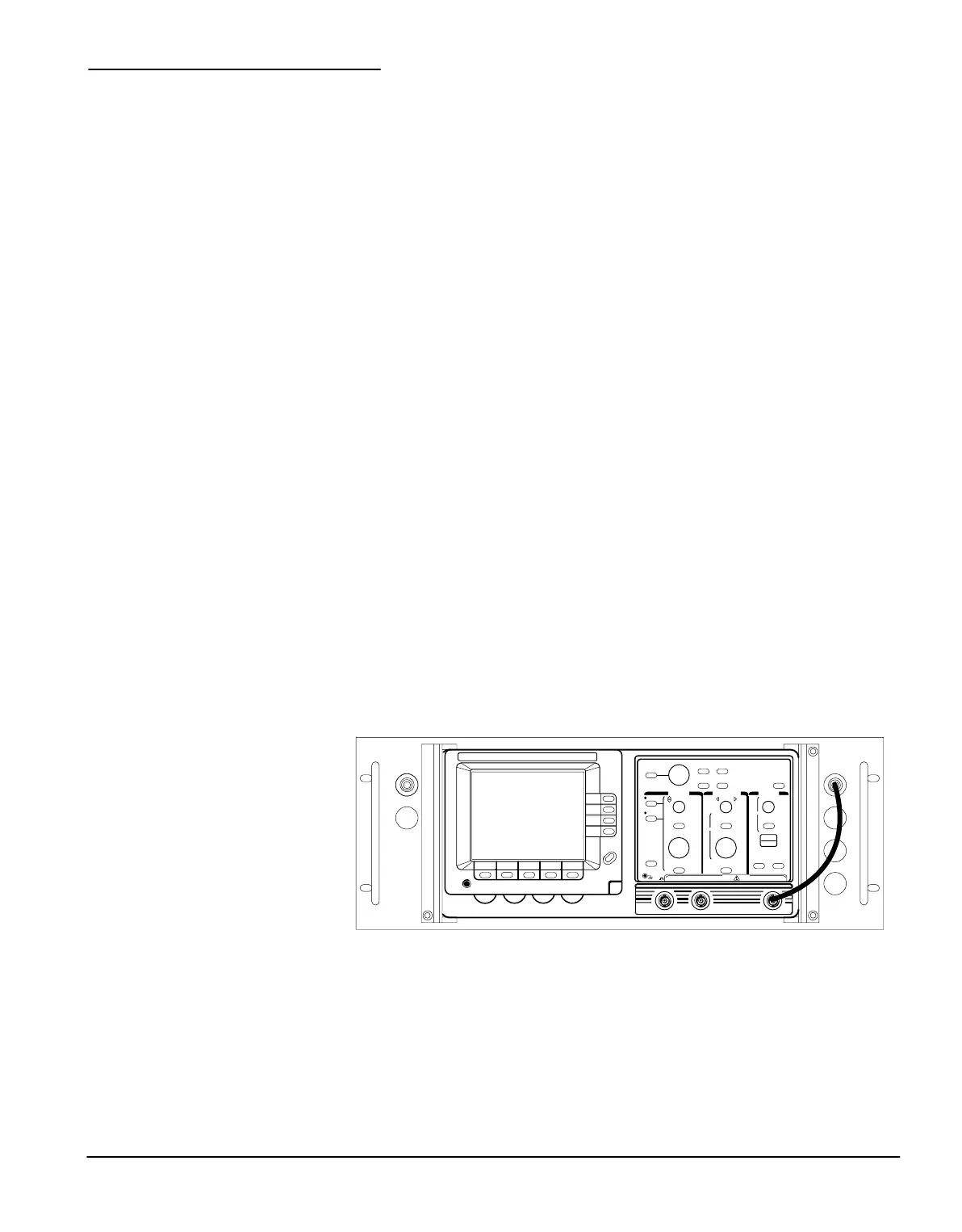
4. Attach a 10Ćinch BNC 50 W cable from the instrument to the installed
BNC connectors (see Figure 16).
 Loading...

