36 MPH200 series video encoders WebUI user manual
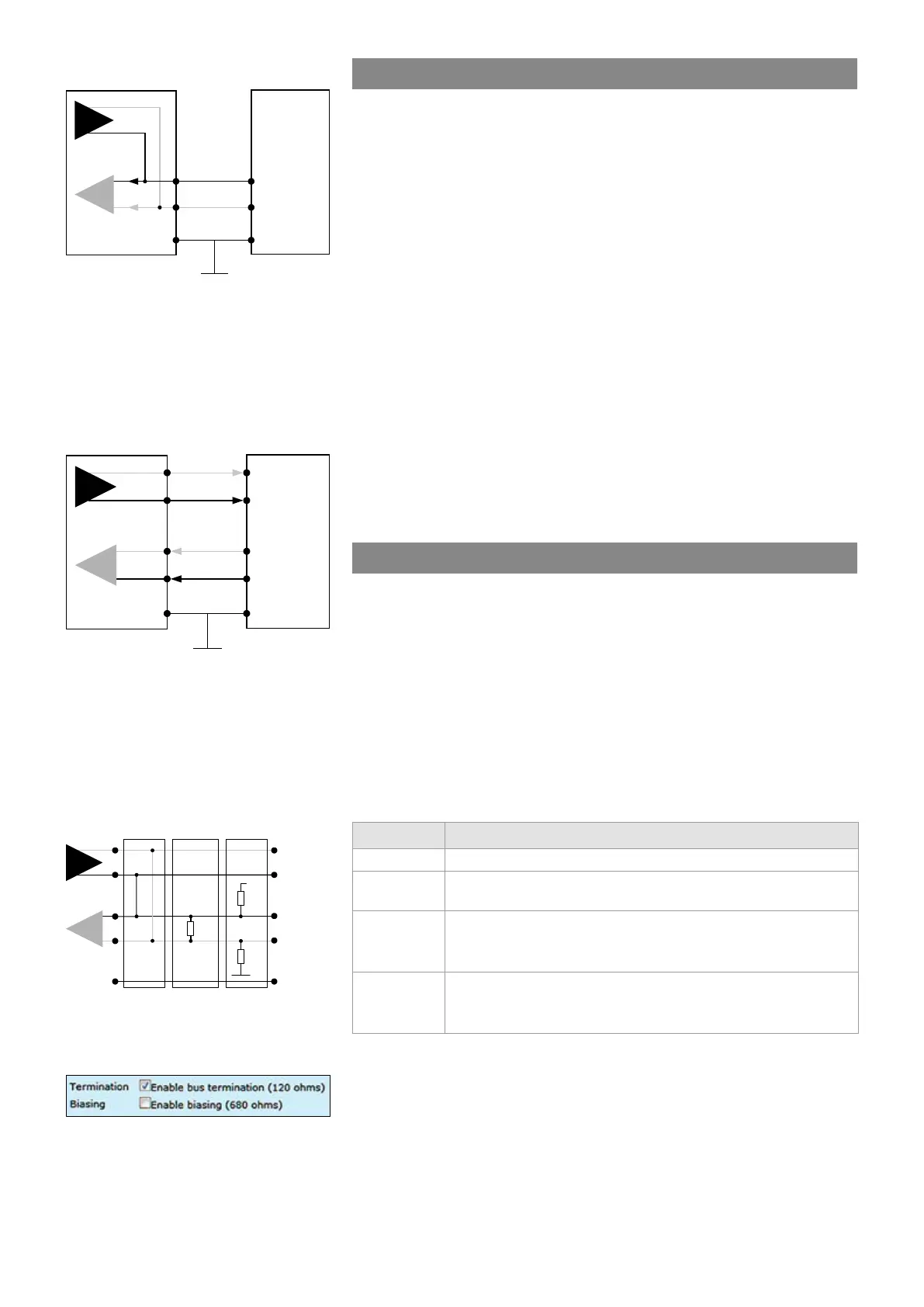
RS485-2w data connection diagram.
A 2-wire RS485 network is implemented
as a half-duplex system using single
twisted-pair cabling. This means that
data can ow in both directions but only
in one direction at a time.
RS422 / RS485-4w data
connection diagram.
A 4-wire RS485 network can be
implemented as a full-duplex system
using two twisted-pair buses where
each bus is used for each direction
of transmission.
MPH’s internal functionality for data
channel 1 termination and biasing.
-
-
+
+
Ground shield
DATA2 TX
6
7
8
DATA2 RX
DATA2 GND
Tx
Rx
Tx / Rx
-
+
+
-
-
+
Ground shield
DATA1 GND
DATA1 IN+
DATA1 OUT+
DATA1 OUT-
DATA1 IN-
Tx
Rx
Tx
Rx
-
-
+
+
1
2
3
4
5
+
-
-
+
DATA1 OUT-
DATA1 IN+
DATA1 IN+
Ground
Tx
Rx
Termination
Biasing
680Ω
+5V
120Ω
680Ω
2-wire
Data type descriptions
RS232 is an unbalanced data format (i.e. the signal wire working
against a reference – ground). Simplex RS232 requires two connections
(signal and ground). Full-duplex RS232 requires three connections
(signal TX, signal RX and ground).
RS422 is a balanced data format. Simplex RS422 requires three data
connections (+/- and ground). Full-duplex RS422 requires ve data
connections (in+/in-, out+/out- and ground).
RS485 is used for full-multipoint communications where multiple trans-
ceiver devices may be connected to a single twisted-pair signal cable.
Most RS485 systems use a Master/Slave architecture, where each
Slave unit has a unique address and responds only to packets
addressed to that unit. Packets are generated by the Master (e.g. CCTV
controller keyboard), which periodically ‘polls’ all connected Slave units
(e.g. CCTV camera receiver units). The Slave unit that has been
addressed then sends the appropriate reply packet back to the Master.
Slave units have no means of initiating communication without the risk
of a collision so they need to be assigned the ‘right to transmit’ by the
Master (by polling). RS485 exists in two versions, 2-wire and 4-wire.
Data termination and biasing
Termination is used to match impedance of a node to the impedance of
the transmission line being used. When impedance are mismatched, the
transmitted signal is not completely absorbed by the load and a portion
is reected back into the transmission line. If the source, transmission
line and load impedance are equal these reections are eliminated.
Biasing -> the lines will be biased to known voltages and nodes will not
interpret the noise from undriven lines as actual data; without biasing
resistors, the data lines oat in such a way that electrical noise sensitiv-
ity is greatest when all device stations are silent or unpowered.
Termination and biasing settings view
from WebUI.
Data input termination options for data channels. Data termination
connects 120 Ω between pins. Hard bias connects 680 Ω (+input) to +5V
and GND (- input).
Data mode Input termination options
RS232 None
RS422
No term (with failsafe)
Line termination (120 Ω)
RS485 - 2w
No term (with failsafe)
Hard bias (forced 680 Ω line biasing)
Line termination (120 Ω)
RS485 - 4w
No term (with failsafe)
Hard bias (forced 680 Ω line biasing)
Line termination (120 Ω)