42 MPH200 series video encoders WebUI user manual
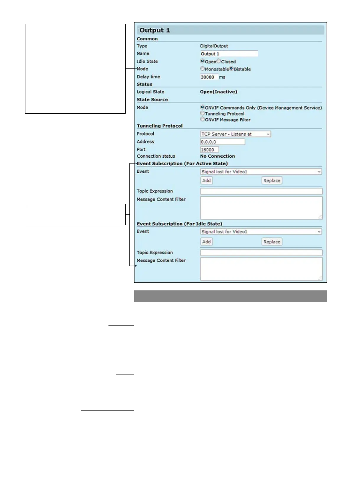
Contact closure output
CC output can be controlled either with ONVIF Commands (SetRelay-
OutputState) or by receiving state using tunneling protocol.
_________________________________________________________
User dened alias name for
contact closure interface (max 64 chars)
User dened default standby mode for contact closure output pins.
Open means that the output relay is open in inactive mode.
Close means the output relay is closed in inactive mode.
Contact closure output state mode, either Monostable or Bistable.
Time period in monostable mode when state changes back to the idle state.
_________________________________________________________
Current CC output state.
_________________________________________________________
Denition how to control the CC output. Options are:
ONVIF Commands only, Tunneling Protocol and ONVIF Message Filter
_________________________________________________________
There are three connection types. Point-to-point (Client/server) based
connection which is done by TCP client / server protocol. If the encoder is
set to be TCP Server, then the decoder or management system must be
set to TCP Client, or vice versa. In UDP multicast mode, you can control
multiple devices and connection can be point to multipoint.
Destination IP address
UDP port number (0...65535). This number has to be same at both encoder
and decoder pairs
Current CC connection status
Common
Name:
Idle State:
Mode:
Delay time:
Status
Logical State:
State Source
Mode:
Tunneling protocol
Protocol:
Address:
Port:
Connection status:
Bistable – After changing the state,
the relay remains in this state.
Monostable – After changing the
state, the relay returns to its idle
state after the specied time.
Note! When Contact closure
tunneling is used, Bistable mode is
only applicable. Monostable mode is
applicable when relay output is
controlled by ONVIF commands
from ONVIF client.
Trigger Conguration
See section “Event management
system” from page 60 for more details.