68 MPH200 series video encoders WebUI user manual
Spanning tree (STP/RSTP) – introduction
The Spanning Tree Algorithm (STA) can be used to detect and avoid
network loops, and to provide backup links between switches, bridges or
routers. This allows the switch to interact with other bridging devices
(that is, an STA-compliant switch, bridge or router) in your network to
ensure that only one route exists between any two stations on the
network, and provide backup links which automatically take over when a
primary link goes down.
The spanning tree algorithms supported by this switch include
these versions:
• STP – Spanning Tree Protocol (IEEE 802.1D).
STP is a standard Layer 2 switch requirement that allows bridges to
automatically prevent and resolve L2 forwarding loops. Switches
exchange conguration messages using specically formatted frames
and selectively enable and disable forwarding on ports.
• RSTP – Rapid Spanning Tree Protocol (IEEE 802.1w).
RTP can take 30-60 seconds for each host to decide whether its ports
are actively forwarding trafc. Rapid Spanning Tree (RSTP) detects
network topologies to achive faster convergence, without creating
forwarding loops.
RSTP conguration
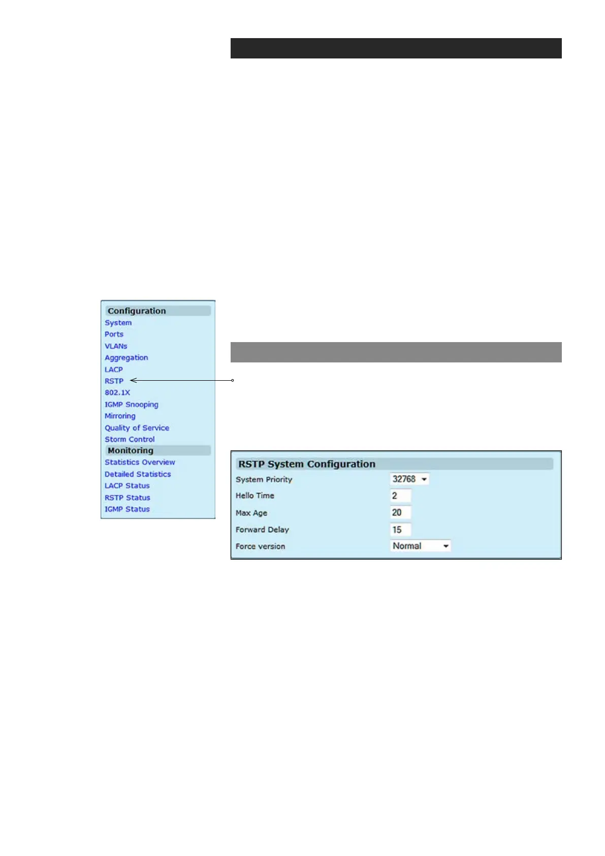
Click “RSTP” under the Conguration menu. RSTP System
Conguration page appears on the screen. The page is composed of
two tables:
• RSTP System Conguration - Congure global system settings.
• RSTP Port Conguration - Setup port related settings.
System Priority:
Hello Time:
Max Age:
Forward Delay:
Force version:
This parameter congures the spanning tree priority globally for this
switch. The device with the highest priority becomes the STA root device.
However, if all devices have the same priority, the device with the lowest
MAC address will then become the root device. Number between
0...61440 in increments of 4096. Therefore, there are 16 distinct values.
Interval (in seconds) at which the root device transmits a conguration
message (BPDU frame). Number between 1...10 (default is 2).
The maximum time (in seconds) a device can wait without receiving a
conguration message before attempting to recongure. That also
means the maximum life time for a BPDU frame. Number between
6...40 (default is 20).
The maximum time (in seconds) the root device will wait before changing
states (i.e., discarding to learning to forwarding). Number between 4...30
(default is 15).
Set and show the RSTP protocol to use.
Normal = use RSTP,
Compatible = compatible with STP.