BRAVO – Wireless Alarm Control Panel
11
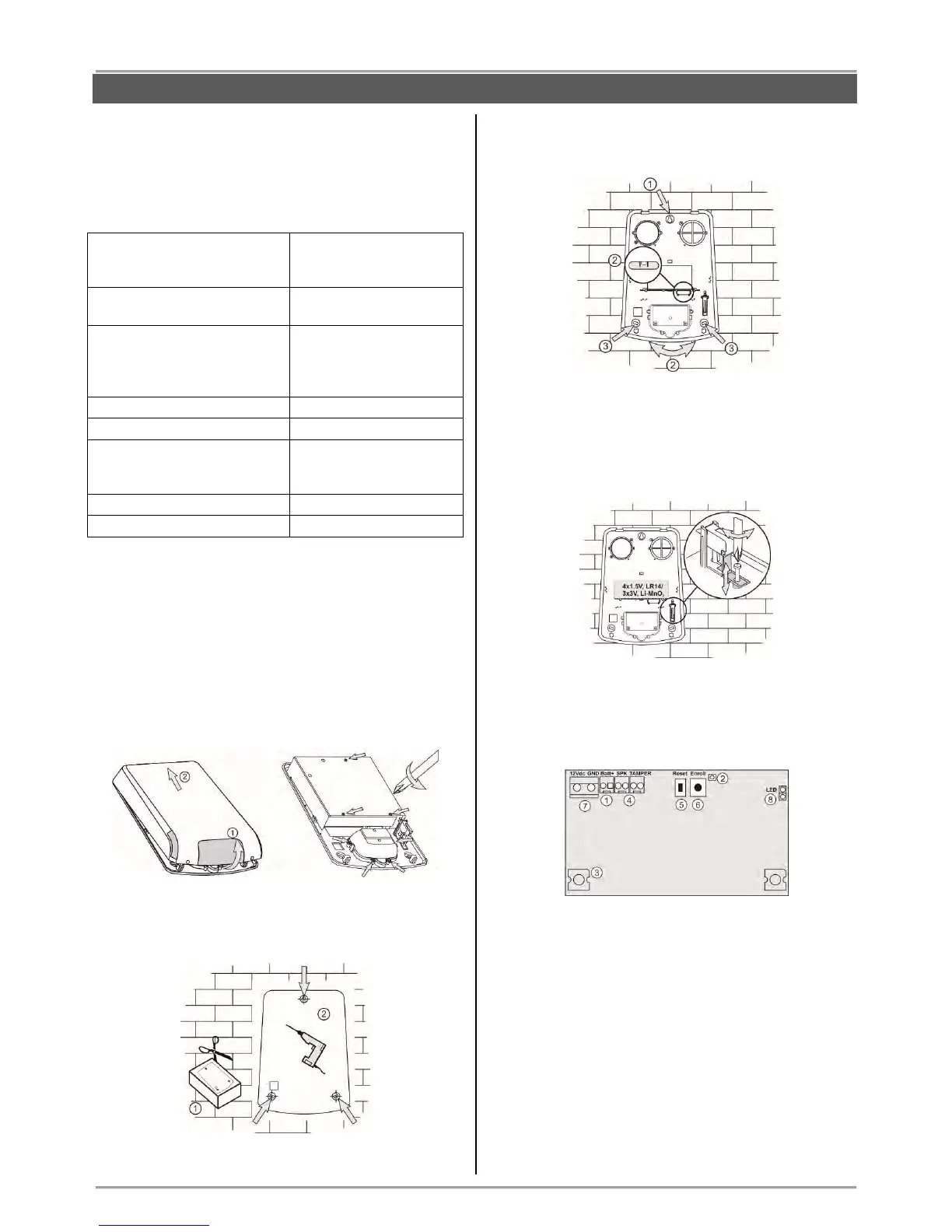
3.7. Mounting of BRAVO SR300
BRAVO SR300 is a wireless piezo siren for outdoor
mounting. The siren is available in two variant according
the type of the used batteries: BRAVO SR300 AKL and
BRAVО SR300 LIT.
Technical Specifications:
* Based on normal use of the siren (e.g. 1 alarm per month with strobe
and 1 minute alarm cycle, and 8 squawks per day at an average of
25°C). If the use is more frequent or the alarm cycle is set for more
than 1 minute the battery life may be reduced.
Using optional power supply with adapter 12V/1A will extend the
battery life.
Mounting
1. Lift up the cover and remove it from the base. Undo
the screws and remove one-by-one the metal and the
plastic covers.
2. Use the drilling template on the back side of the
packing box to mark and drill the holes for installation.
3. Mount the siren base as first fix the screw for the
main installation hole, then lever the siren, and at the
end fix the supporting screws on the both sides.
4. Set the tamper position as use the screw on it -
regulate the position so that the screw end to contact
with the installation surface, and the contact plate to be
pressed when the cover of the siren is closed (the plate
must be horizontal and when pressed with siren cover
to close the tamper button under it - a click is heard).
5. Enroll the siren to the panel configuration as follow
the steps described at item 6.4 in “System
Configuration” section.
Description of the PCB elements
1 – Terminal for connecting the battery.
2 - LED for siren status.
3 – LED signalization in Alarm mode; Optional LED
signalization in standby mode (“chasing LEDs” type).
4 - Terminals SPK (SPEAKER) and TAMPER for
connecting the sounder and tamper button wires.
5 – ENROLL button. Use it to enroll the siren to the
panel.
6 – RESET Button. Use it to reset the detector.
7 – Terminals +12VDC and GND for optional power
supply with adapter 12VDC/ 1A – see also item 10.4.
8 – LED Terminals. Set a jumper to switch on the
optional “chasing LEDs” signalization.
Attention: Using the optional “chasing LEDs”
signalization in standby mode will reduce the battery
life.