BRAVO – Wireless Alarm Control Panel
13
3.9. Mounting of BRAVO FD
BRAVO FD is wireless combined fire alarm detector
with optical-smoke and heat (rate-of-rise) parts.
Technical Characteristics:
2 х 3 V/ 1500mAh,
CR123A type
Battery life
(max. without LED)
Radio distance
(open space)
Dimensions
(including base)
Rate-of-rise 10ºC/ min
(max 60ºC)
Class for the heat part,
according EN54-5
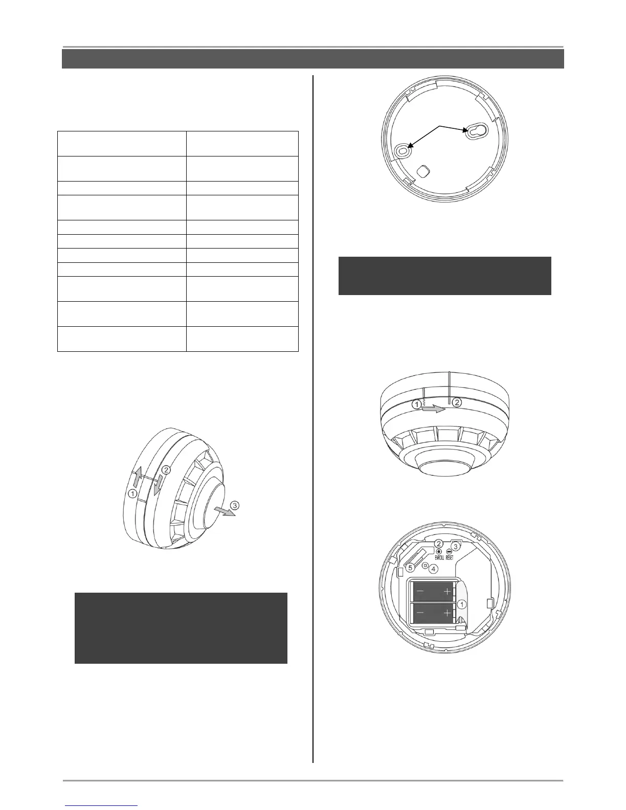
Mounting
1. Remove the detector from the base as rotate both
parts opposite to each other – the base clockwise and
the detector counter clockwise.
2. Mount the base at the place of installation.
ATTENTION: Avoid placing the detector close to
the following sources of interference:
- heated surfaces;
- direct air flows from chimneys, windows, fans
and sources of evaporation
- smoke, ash and other contaminators.
3. Enroll the detector to the panel configuration as follow
the steps described at item 6.2 in “System
Configuration” section.
Note: You can enroll BRAVO FD to every
position (zone number) from 3 to 16, as the “24-
fire zone” zone type is set automatically.
4. Mount the detector back to the base – locate the
marker on the outer side of the detector’s body to
coincide with the short pin on the outer side of the base.
Then rotate the detector clockwise until the marker
coincides with long pin on the outer side of the base.
Description of the PCB elements
1 – Protection folio for the batteries; it is removed
directly before the enrolment of the detector to the
panel.
2 – ENROLL Button. Use it to enroll the detector to the
panel.
3 – RST (RESET) Button. Use it to reset the detector.
4 – LED for the current status of the detector
5 – Tamper button for self-protection.