BRAVO – Wireless Alarm Control Panel
16
3.11.1. BRAVO GPRS Module
Mounting
1. Remove the cover of the panel – see item 3.1. Switch
off the main and backup power supply.
Mount BRAVO GPRS module to Slot 1 or Slot 2 on the
main PCB.
2. Fix the module with screws to the panel’s PCB.
3. Place a SIM card as shown on the picture.
ATTENTION: The PIN check option of the SIM
card must be disabled!
4. Switch on the main and backup power supply and
close the cover of the box.
5. Use the ProsTE software (see the connection
between the panel and PC in item 7.9) to enable the
module for operation and to set additional parameters if
needed.
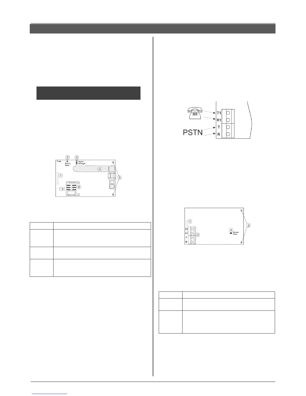
Description of the PCB elements
1 – An interface connector for coupling with the panel’s
PCB (on the back side of the module PCB).
2 – LED indication for the module status:
Problem with the SIM card; problem with the
GPRS channel; no communication between
the module and the server.
The module is sending messages via back-up
channel.
The module is in normal operation mode (the
connection with the server is stable and the
transmitting of messages is successful).
3 – LEDs for radio signal strength:
- All OFF: No signal.
- 1 LED lighting: Low signal.
- 2 LEDs lighting: Good signal.
- 3 LEDs lighting: Very good signal.
4 – Antenna.
5 – Mounting holes.
6 – Holder for the SIM card.
3.11.2. BRAVO PSTN Module
Mounting
1. Remove the cover of the panel – see item 3.1. Switch
off the main and backup power supply.
Mount BRAVO PSTN module to Slot 1 or Slot 2 on the
panel’s PCB.
2. Fix the module with screws to the panel’s PCB.
3. Connect the telephone line to the terminals Т and R,
and the telephone device to terminals T1 and R1. There
are no requirements for the polarity of the connection.
4. Switch on the main and backup power supply and
close the cover of the box.
5. Use the ProsTE software (see the connection
between the panel and PC in item 7.9) to enable the
module for operation and to set additional parameters if
needed.
6. Perform communicator test as described in item 9.7.
Description of the PCB elements
1 – An interface connector for coupling with the panel’s
PCB (on the back side of the module PCB).
2 – Mounting holes.
3 – Terminals for connecting of telephone line and
device.
4 - LED indication for the module status:
The telephone line is missing. The module
is unable to send message for an event.
The module is in normal operation mode
(the connection with the telephone line is
stable and the transmitting of messages is
successful).