BRAVO – Wireless Alarm Control Panel
17
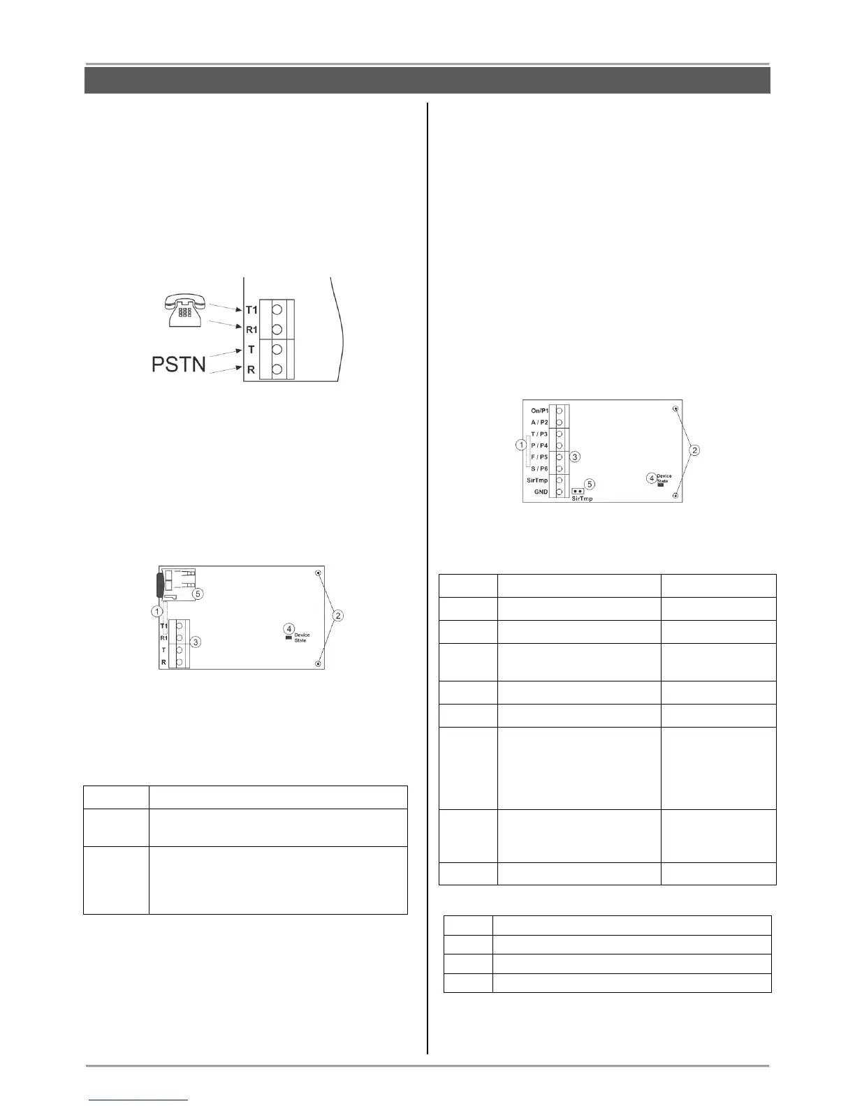
3.11.3. BRAVO PSTN VD Module
Mounting
1. Remove the cover of the panel – see item 3.1. Switch
off the main and backup power supply.
Mount BRAVO PSTN VD module to Slot 1 or Slot 2 on
the panel’s PCB.
2. Fix the module with screws to the panel’s PCB.
3. Connect the telephone line to the terminals Т and R,
and the telephone device to terminals T1 and R1. There
are no requirements for the polarity of the connection.
4. Switch on the main and backup power supply and
close the cover of the box.
5. Use the ProsTE software (see the connection
between the panel and PC in item 7.9) to enable the
module for operation and to set additional parameters if
needed.
6. Perform communicator test as described in item 9.7.
Description of the PCB elements
1 – An interface connector for coupling with the panel’s
PCB (on the back side of the module PCB).
2 – Mounting holes.
3 – Terminals for connecting of telephone line and
device.
4 - LED indication for the module status:
The telephone line is missing. The module
is unable to send message for an event.
The module is in normal operation mode
(the connection with the telephone line is
stable and the transmitting of messages is
successful).
5 – Holder with a mini SD card. The voice messages for
events are recorded to the mini SD card.
3.11.4. BRAVO MOUT Module
Mounting
1. Remove the cover of the panel – see item 3.1. Switch
off the main and backup power supply.
Mount BRAVO MOUT module to Slot 1 or Slot 2 on the
panel’s PCB.
2. Fix the module with screws to the panel’s PCB.
3. Connect the outputs of the module according the
application of the module.
ATTENTION: The functionality of the outputs can be set
in one of two operation modes using ProsTE software:
- MOUT – Transmitting signals to radio transmitter or
connecting of wired siren (see Examples 1 and 2).
- PGM – Programmable outputs OC, 100mA.
4. Switch on the main and backup power supply and
close the cover of the box.
Description of the PCB elements
1 – An interface connector for coupling with the panel’s
PCB (on the back side of the module PCB).
2 – Mounting holes.
3 – Terminal row:
Event “Tamper / Lost
device”.
Event “Siren” – repeats
the alarm cycle of a
connected wired siren
(the silent alarms do not
affect at this output).
Jumper for disabling the
signals from a wired siren
connected to the module.
4 - LED indication for the module status:
Power-up initialization mode.
No communication with the panel.
The module is in normal operation mode.
5 – Jumper SirTmp (see the connection diagram
between BRAVO MOUT and wired siren in Application
Example 2).