BRAVO – Wireless Alarm Control Panel
6
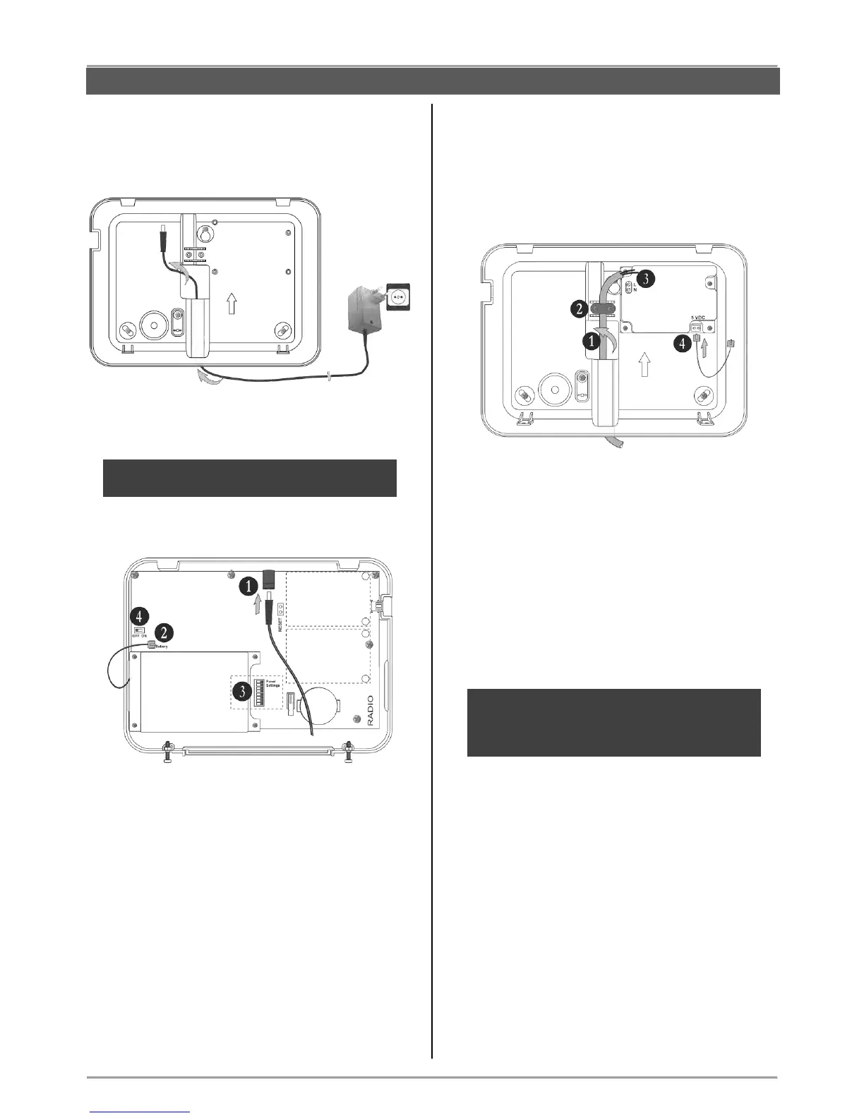
3.2. Mounting and connection of
BRAVO EXT
Run the connector of the power adapter through the
main cable channel and lead it on the internal side of
the bottom.
The cable length of the power adapter is ~1700mm,
so you have to locate the panel installation place
near a power socket.
Prepare the panel for connecting to the mains power
230V.
1. Connect the power adaptor connector to the
input on the panel’s PCB.
2. The cable of the battery must be connected
to the “Battery” terminal.
3. Set the dip-switches position according the
system configuration – see the section
“Hardware settings” (item 4).
4. Switch on the battery – set the mini switch in
“ON” position.
Close the panel’s box following the steps in item 3.1
in a reverse order.
Plug in the power adapter in the socket and proceed
with peripheral device enrolment – see the section
“System Configuration” (item 6).
3.3. Mounting and connection of
BRAVO INTR
BRAVO INTR is a wireless alarm panel with built-in
power supply unit, which is factory mounted to the
bottom of the box.
Prepare the panel for connecting to the mains power
230V.
1. Run the mains power supply cable through
the main cable channel and lead it on the
internal side of the bottom.
2. Fix the mains power cable to the bottom
using the plastic cap and screws from the spare
parts kit.
3. Connect the mains power cable to the “L N”
terminal as observe the polarity.
4. Assure that a special cable is connected to
“5VDC” terminal.
Note: Position the cable for 5 VDC power
supply as shown on the picture and observe
keeping this position when you close the
BRAVO INTR box!
The installer should strictly observe the polarity of
the electrical connection when connecting the power
cable to “L N” terminal. The ends of the power cable
should be clearly stripped and fixed tightly to the
terminal of the power supply unit – use a plain
screwdriver to tight the screws.