Connect the cable on “5VDC” terminal to the same
terminal on the panel’s PCB.
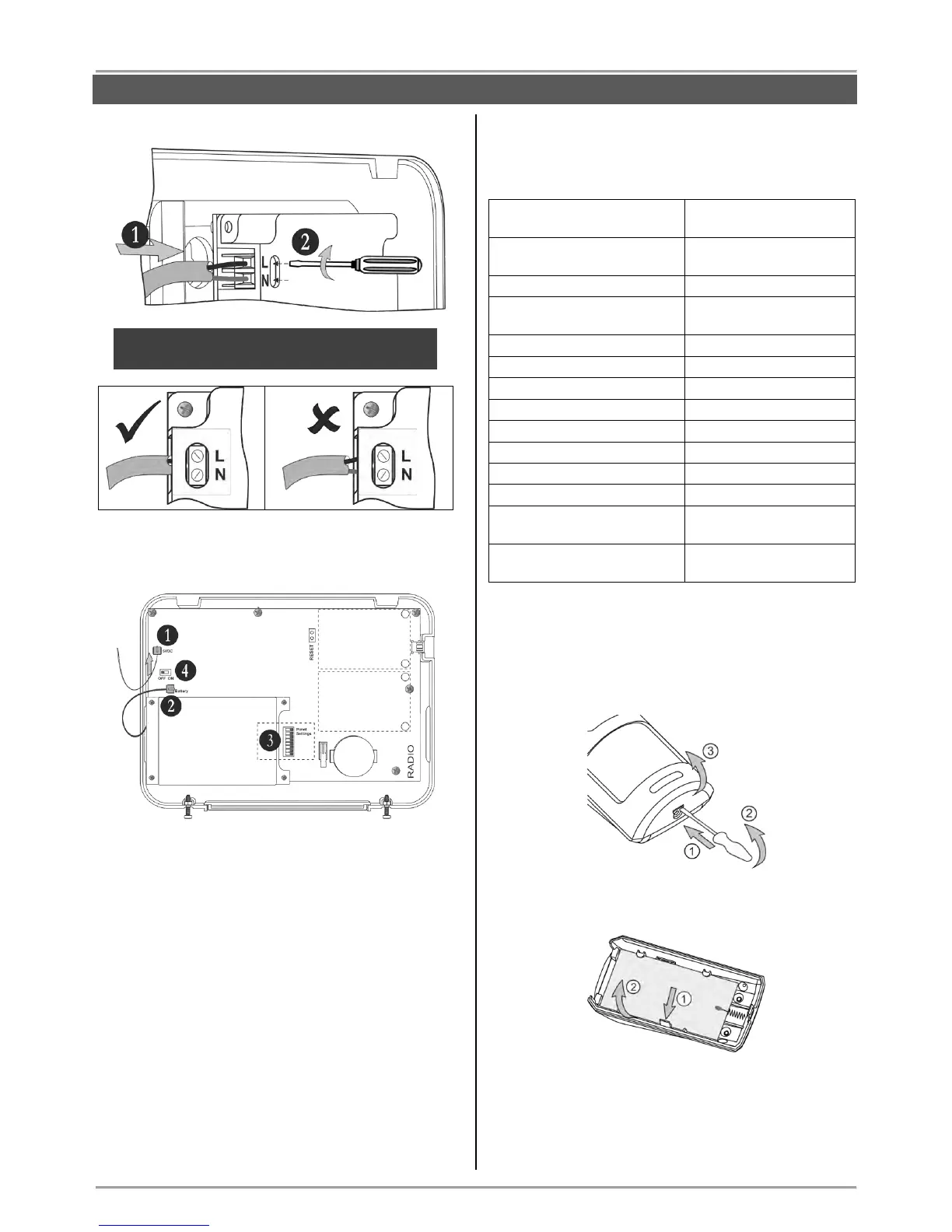
1. Connect the cable on “5VDC” terminal of the
power supply unit to the “5VDC” terminal on the
panel’s PCB.
2. The cable of the battery must be connected
to the “Battery” terminal.
3. Set the dip-switches position according the
system configuration – see the section
“Hardware settings” (item 4).
4. Switch on the battery – set the mini switch in
“ON” position.
Close the panel’s box following the steps in item 3.1
in a reverse order.
Switch on the mains power supply and proceed with
peripheral device enrolment – see the section
“System Configuration” (item 6).
3.4. Mounting of BRAVO PIR
BRAVO PIR is a wireless passive infrared detector for
detecting of movement.
Technical Characteristics:
Mounting
1. Open the detector box as use small plain screwdriver
– use a small flat screwdriver and slightly press at the
opening in the bottom side and then open the cover up.
2. Remove the detector PCB by pressing the clip
downward and pull it out.
3. Mount the detector at the place of installation. Use
the respective opening according the mounting location
– on a wall or in a corner.