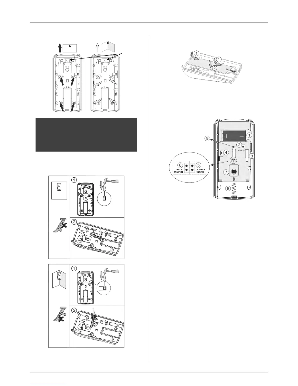
ATTENTION: When the detector is installed
on a mounting bracket, it is impossible to use
the second tamper-switch for self-protection
(on the back side of the PCB) and the
requirements of standard EN50131 Grade 2
are not covered!
Use the elements for the second tamper-switch,
according the place of installation:
4. Mount the PCB back onto the base by placing it first
on the front clips.
5. Enroll the detector to the panel configuration as follow
the steps described at item 6.2 in “System
Configuration” section.
Description of the PCB elements
1 – Protection folio for the battery; it is removed directly
before the enrolment of the detector to the panel.
2 – ENROLL Button. Use it to enroll the detector to the
panel.
3 – The first tamper-button for self-protection. Used for
signaling in case of removing the detector’s cover.
4 – RST (RESET) Button. Use it to reset the detector.
5 – DOUBLE KNOCK Jumper (“Double knock”
operation mode). Set a jumper on the terminals (on the
right side) to activate the “Double knock” operation
mode.
6 - BACK TAMPER Jumper (follows the state of the
second tamper-switch for self-protection). Set a jumper
on the terminals (at the left side) to enable the operation
of the second tamper-switch.
7 – Motion sensor.
8 - Antenna.
9 – The second tamper-button for self-protection. Used
for signaling in case of removing the detector’s box from
the mounting surface – it is enabled when there is a
jumper set at BACK TAMPER terminals.