7.3. Microphone connector
Figure 7.1: Connector pin layout (bottom view)
− pin 1 : microphone GND
− pin 2 : microphone signal
− pin 3 : unused
− pin 4 : LED +
− pin 5 : LED -
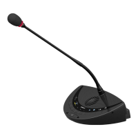
7.4. Operation
The microphone contains the following elements
(refer to Figure 7.2):
1. Indicator ring: shows the status of the
microphone
2. Union nut: attaches the pluggable
microphone to the unit
3. Microphone plug: connects the
microphone to the unit
Figure 7.2: Microphone