- 6 -
- Only use electrodes that are recommended for the machine (see spare parts
list) without altering their shape.
- RISK OF BURNING
Someofthespotwelderparts(electrodes-armsandadjacentareas)can
reach temperatures of above 65°C: suitable protective clothing must be
worn.
Allownewly-weldedpiecestocoolbeforetouchingthem!
- RISK OF TOPPLING AND FALLS
- Place the spot welder on a horizontal surface that can suitably support the
mass; constrain the spot welder to the supporting surface (when indicated
inthe“INSTALLATION”sectionofthismanual).Incontrarycases,where
theooringisslopedorbroken,orwithmobilesupportingsurfaces,the
danger of toppling exists.
- It is forbidden to lift the spot welder, excluding where expressly indicated in
the“INSTALLATION”sectionofthismanual.
- When using machines on wheels: disconnect the spot welder from the
electric and pneumatic (if present) power supplies before moving the unit
to another work area. Pay attention to obstacles and unevenness on the
ground (for example cables and piping).
- UNINTENDED USE
It is dangerous to use the spot welder for any purpose other than that for
which it is intended (see INTENDED USE).
SAFEGUARDS AND SHIELDS
The safeguards and mobile parts of the spot welder casing must be in position,
before connecting it to the power supply.
WARNING!Anymanualinterventionontheaccessiblemobilepartsofthespot
welder,forexample:
- Replacement of or maintenance on the electrodes
- Adjustmentofthearmorelectrodepositions
MUST BE CARRIED OUT WITH THE SPOT WELDER SWITCHED OFF AND
DISCONNECTEDFROMTHEELECTRICANDPNEUMATIC(ifpresent)POWER
SUPPLY.
MAINSWITCHLOCKEDAT“O”WITHLOCKCLOSEDANDKEYREMOVEDinthe
modelswithPNEUMATICCYLINDERmovement).
STORAGE
- Place the machine and its accessories (with or without packaging) in closed
areas.
- Therelativehumidityoftheairmustnotexceed80%.
- The environmental temperature must be between -15°C and 45°C.
If the machine has a water cooling unit and the environmental temperature is
lower than 0°C: add the indicated antifreeze liquid or completely empty the
hydraulic circuit and the water tank.
Always use suitable measures for protecting the machine from humidity, dirt
and corrosion.
2. INTRODUCTION AND GENERAL DESCRIPTION
2.1 MAIN CHARACTERISTICS
Column spot welding machine with electrode and curved descent for resistance
weldingsystem(singlespot)withdigitalmicroprocessorcontrol.
Their main characteristics are:
- limitationoflineovercurrentatinsertion(insertioncosφcheck);
- choiceofthebestspotweldingcurrentaccordingtothemainspoweravailable;
- choice of the optimal welding cycles parameters (approach time, ramp time,
weldingtime,pausetimeandpulsenumber);
- savingoffavouriteprogrammes;
- backlitLCDdisplaythatshowsthecontrolsandthesetparameters;
- thermalprotectionwithindicator(overloadorlackofcoolingwater);
- indicatingandblockingintheeventofoverloadorunderloadofdeliveredvoltage;
- noairindicator(onlyonPCPpneumaticcontrolmodels);
- airowregulationforslowarmclosing(onlyonPCPpneumaticcontrolmodels).
Operation:
- ”PTE”models:mechanical,equippedwithpedalwithadjustableleverlength;
- ”PCP”models:pneumatic,equippedwithdoubleeffectcylindercontrolledbya
pedal valve.
2.2 OPTIONAL ACCESSORIES
- Armpair,length500mm,completewithelectrodeholdersandstandardelectrodes.
- Armpair,length700mm,completewithelectrodeholdersandstandardelectrodes.
- Curvedelectrodes.
- Closedcircuitwatercoolingsystem(suitableforPTEorPCP18only).
3. TECHNICAL DATA
3.1 RATING PLATE (FIG. A)
Themaindatarelatingtouseandperformanceofthespot-welderaresummarisedon
the rating plate and have the following meanings:
1- Numberofphasesandfrequencyofpowersupply.
2- Powersupplyvoltage.
3- Mainspowerwithpermanentrunning(100%).
4- Ratedmainspowerwith50%dutycyde.
5- Maximumloadlessvoltageoverelectrodes.
6- Maximumcurrentwhenelectrodesareshorted.
7- Currenttosecondarywhenrunningpermanently(100%).
8- Gaugeandlengthofarms(standard).
9- Minimumandmaximumadjustableelectrodeforce.
10- Ratedpressureofcompressedairsupply.
11- Pressureofcompressedairsupplyneededtoobtainmaximumelectrodeforce.
12- Coolingwaterowrate.
13- Ratedpressuredropforcoolantliquid.
14- Weight of welding device.
15- Safetysymbols,themeaningsofwhicharegiveninchapter1“Generalsafety
rulesforresistancewelding”.
Note:Theratingplateshownisanexampletoshowthemeaningofthesymbolsand
numbers;theexacttechnicalspecicationsofyourspot-weldercanbefoundonthe
rating plate of the spot-welder itself.
3.2 OTHER TECHNICAL DATA (FIG. B)
4.DESCRIPTIONOFTHESPOT-WELDER
4.1SPOT-WELDERASSEMBLYANDDIMENSIONS(FIG.C)
4.2 CONTROL AND ADJUSTMENT DEVICES
4.2.1 Control panel (FIG. D1).
1- main switch (inPCPmodels withemergencystop functionand lockfunctionin
position“O”:lockandkeysupplied).
2- increase(+)decrease(-)buttons.
3- “MODE”settingsselectorbutton.
4- rear-litLCDdisplay;
5- run/STARTbutton(mod.PCP);
6-
/ pressureonlyswitch(nowelding)/welding.
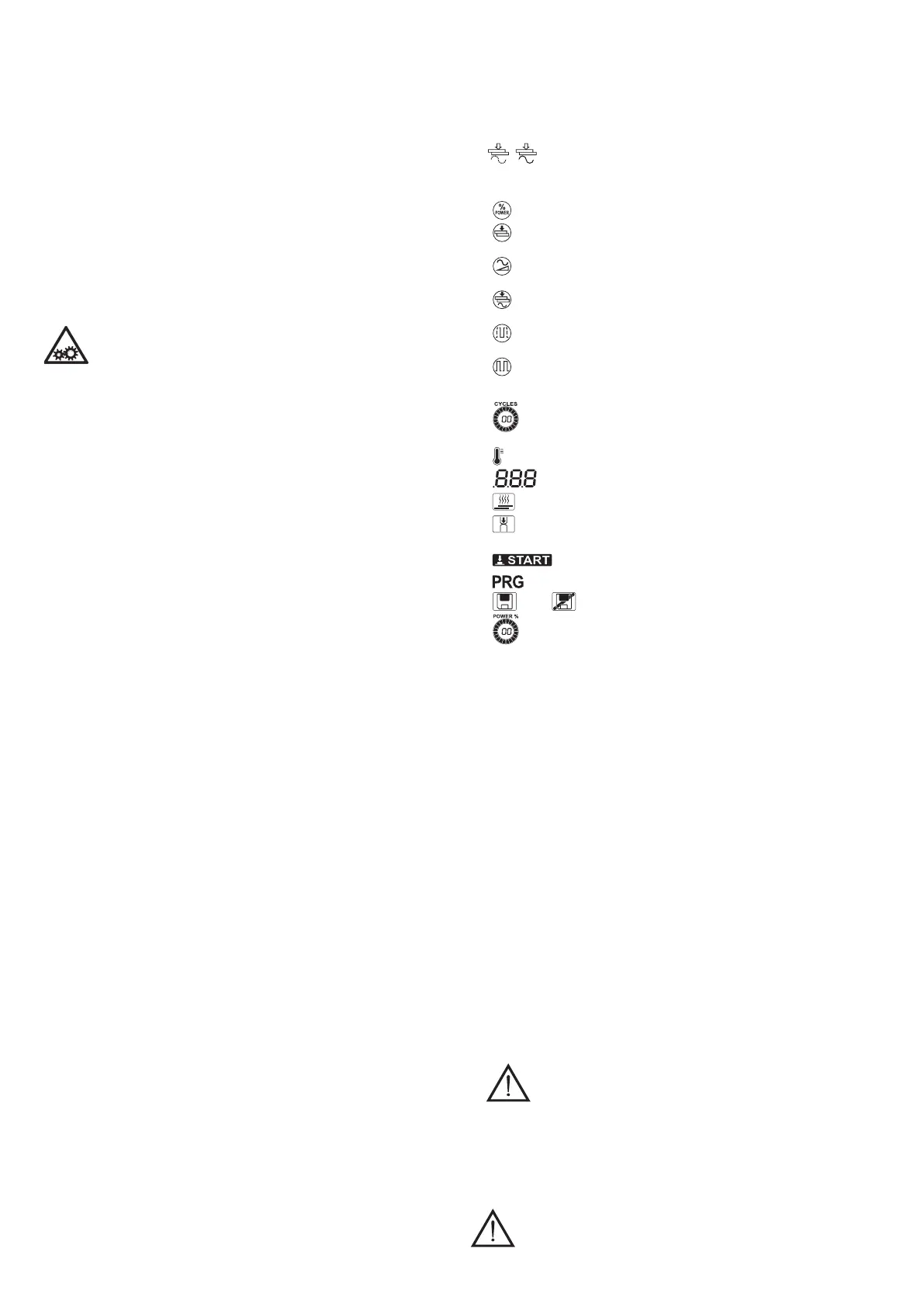
4.2.2 Description of the icons (FIG. D2).
Spot welding parameters (1-7):
1-
power(%):spotweldingcurrentasapercentageofthemaximumvalue;
2-
approach(cycles):stand-bytimesincyclesbeforedeliveringcurrentfromthe
contactoftheelectrodeswiththepiecebeingprocessed;
3-
ramp(cycles):timeincyclesthatthespotweldingcurrenttakestoreachthe
valuesetfor“power”;
4-
spotweldingtime(cycles):timeincyclesthatthecurrentremainsattheset
value;
5-
pausetime(cycles):timeincyclesduringwhichthecurrentiszerobetween
onepulseandanother(onlyinpulsemode);
6-
pulsenumber(n°):if1thenthespotweldingstopsafterspotweldingtime(4);
if greater than 1, it indicates the number of current pulses delivered by the
machine(pulsemode);
7-
circular synoptic indicator, with numerical value inthe centre, of the set
cycles;
8-
thermalalarmicon;
9-
multifunctionnumericaldisplay;
10-
spotweldingenabledicon(deliveryofcurrent);
11-
approach enabled icon, with selector switch in FIG. D1-6 in the NO
WELDINGposition;
12-
STARTindicator:pressthebuttoninFIG.D1-5tostartthemachine;
13-
customisedPROGRAMMEicon;
14-
save / donotsavecustomisedprogrammeicon;
15-
circular synoptic indicator, with numerical value inthe centre, of the set
power.
4.2.3 Setting of the spot welding parameters
Eachtimethemachineisswitchedon,andbeforepressingthe“START”button,itis
possibletochangethefunctionmodeusedtosettheweldingparameters:
- “REDUCED”=EASYmode: allowsquickand user-friendlyselectingof the two
mainspotweldingparameters“POWER”(1)and“weldingtime”(4).Thisfunction
modedoesnotforeseethesavingofcustomisedprogrammes.
- “EXTENDED” = EXPERT mode: allows the selecting of all the welding parameters
described in the paragraph above. This function mode allows the saving of
customisedprogrammes.
4.2.4Compressionandowregulatornut(FIG.D3)
1- The nut can be accessed via the hatch door on the rear of the spot welding
machine.
Thenutisusedtoregulatetheforceexertedbytheelectrodesinterveningonthe
springpreload:thegreaterthespringload,thegreatertheforceofthespotwelding
machine electrodes.
2- Theowregulator(PCPmod.only)isusedtodecreasethearmclosurespeedto
preventtheelectrodesfromreboundingonthepiece.
Rotatetheadjusterscrewcounterclockwise(+)toincreaseairowanddescent
speedoftheelectrodes;rotatethescrewclockwise(-)todecreaseairowandthe
descent speed of the electrodes.
4.2.5 Pressure and pressure gauge regulation (FIG. D4 - PCP mod. only)
1- Pressureregulatorknob;
2- Pressuregauge.
4.2.6 Air and water couplings (FIG. G and H)
G(1)-Compressedairpipecoupling(PCPmod.only);
G(2)-Condensatelterandbleeder(PCPmod.only);
H(1)-INLETwatercouplings.
H(2)-OUTLETwatercouplings.
4.3SAFETYFUNCTIONSANDINTERLOCK
4.3.1 Main switch
- Position“O”=openandlockable(seechapter1).
ATTENTION! The internal power cable connection terminals
(L1+L2)arelivewhenturnedtothe“O”position.
- Position“I”=closed:spotweldingmachinepoweredupbutnotoperating(STAND
BY)displayON.
Emergency function
Opening the spot welding machine when it is operating (position “I” => position “O”) will
instantlystopthemachineinsafeshutdownmodewith:
- currentinhibited;
- allmovementisblocked:exhaustercylinder(ifinstalled);
- automaticrestartinhibited.
ATTENTION! PERIODICALLY MAKE SURE THE SAFE SHUTDOWN
FUNCTIONOPERATESCORRECTLY.
 Loading...