DMA Memory Access
www.ti.com
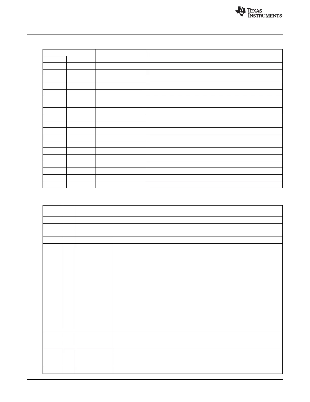
Table 8-1. DMA Trigger Sources (continued)
DMA Trigger
Functional Unit Description
Number Name
14 URX0 USART 0 USART 0 RX complete
15 UTX0 USART 0 USART 0 TX complete
16 URX1 USART 1 USART 1 RX complete
17 UTX1 USART 1 USART 1 TX complete
18 FLASH Flash controller Flash data write complete
19 RADIO Radio (not in CC2540) CC253x: RF packet byte received (see Section 23.3)
CC2541: Radio DMA trigger 0 (see Section 25.3.2)
20 ADC_CHALL ADC ADC end of a conversion in a sequence, sample ready
21 ADC_CH11 ADC ADC end of conversion channel 0 in sequence, sample ready
22 ADC_CH21 ADC ADC end of conversion channel 1 in sequence, sample ready
23 ADC_CH32 ADC ADC end of conversion channel 2 in sequence, sample ready
24 ADC_CH42 ADC ADC end of conversion channel 3 in sequence, sample ready
25 ADC_CH53 ADC ADC end of conversion channel 4 in sequence, sample ready
26 ADC_CH63 ADC ADC end of conversion channel 5 in sequence, sample ready
27 ADC_CH74 ADC ADC end of conversion channel 6 in sequence, sample ready
28 ADC_CH84 ADC ADC end of conversion channel 7 in sequence, sample ready
29 ENC_DW AES AES encryption processor requests download of input data
30 ENC_UP AES AES encryption processor requests upload of output data
31 DBG_BW Debug interface Debug interface burst write
Table 8-2. DMA Configuration Data Structure
Byte
Bit Name Description
Offset
0 7:0
SRCADDR[15:8]
DMA channel source address, high
1 7:0
SRCADDR[7:0]
DMA channel source address, low
2 7:0
DESTADDR[15:8]
DMA channel destination address, high. Note that flash memory is not directly writable.
3 7:0
DESTADDR[7:0]
DMA channel destination address, low. Note that flash memory is not directly writable.
4 7:5
VLEN[2:0]
Variable-length transfer mode. In word mode, bits 12:0 of the first word are considered as
the transfer length.
000: Use LEN for transfer count
001: Transfer the number of bytes/words specified by the first byte/word + 1 (up to a
maximum specified by LEN). Thus, the transfer count excludes the length
byte/word.
010: Transfer the number of bytes/words specified by the first byte/word (up to a
maximum specified by LEN). Thus, the transfer count includes the length byte/word.
011: Transfer the number of bytes/words specified by the first byte/word + 2 (up to a
maximum specified by LEN).
100: Transfer the number of bytes/words specified by the first byte/word + 3 (up to a
maximum specified by LEN).
101: Reserved
110: Reserved
111: Alternative for using LEN as the transfer count
4 4:0
LEN[12:8]
The DMA channel transfer count
Used as the maximum allowable length when VLEN differs from 000 and 111. The DMA
channel counts in words when in WORDSIZE mode, and in bytes otherwise.
5 7:0
LEN[7:0]
The DMA channel transfer count
Used as the maximum allowable length when VLEN differs from 000 and 111. The DMA
channel counts in words when in WORDSIZE mode, and in bytes otherwise.
6 7
WORDSIZE
Selects whether each DMA transfer is 8-bit (0) or 16-bit (1).
102
DMA Controller SWRU191C–April 2009–Revised January 2012
Submit Documentation Feedback
Copyright © 2009–2012, Texas Instruments Incorporated
 Loading...


