FCC Warning
www.ti.com
FCC Warning
This equipment is intended for use in a laboratory test environment only. It generates, uses, and can
radiate radio frequency energy and has not been tested for compliance with the limits of computing
devices pursuant to subpart J of part 15 of FCC rules, which are designed to provide reasonable
protection against radio frequency interference. Operation of this equipment in other environments may
cause interference with radio communications, in which case the user at his own expense will be required
to take whatever measures may be required to correct this interference.
If You Need Assistance
All technical support is channeled through the TI Product Information Centers (PIC) - www.ti.com/support.
To send an E-mail request, please enter your contact information, along with your request at the following
link – PIC request form.
Also visit the Low Power RF, ZigBee, and Bluetooth low-energy sections of the TI E2E Community
(www.ti.com/lprf-forum), where you can easily get in touch with other CC253x and CC2540/41 users and
find FAQs, Design Notes, Application Notes, Videos, etc.
You can also see the TI Knowledgebase for Analog & Mixed-Signal.
Glossary
Abbreviations used in this user guide can be found in Appendix A.
Devices
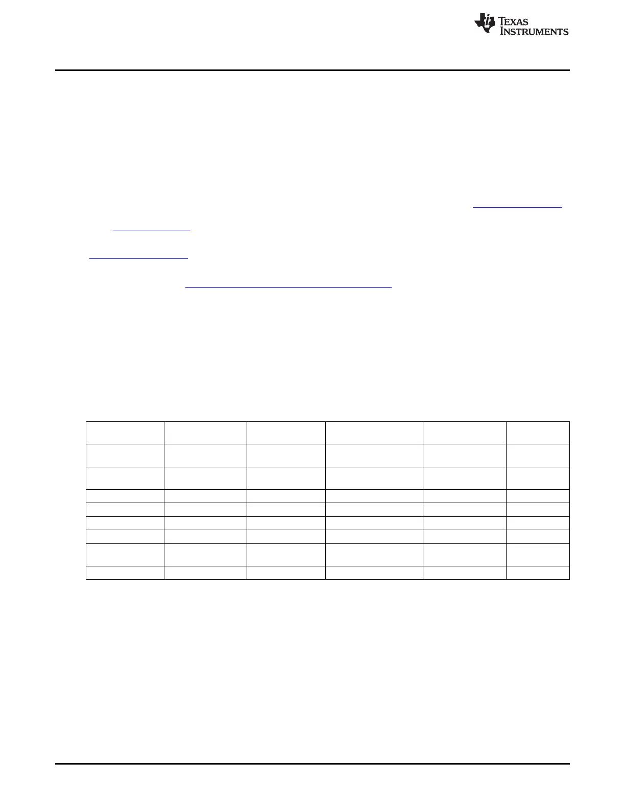
The CC253x System-on-Chip solution family consists of several devices. The following table provides a
device overview and points out the differences regarding memory sizes and peripherals. For a complete
feature list of any of the devices, see the corresponding data sheet (Appendix C).
Table 0-1. CC253x Family Overview
CC2530F32/F64/ CC2540F128/ CC2541F128/
Feature CC2531F128/F256 CC2533F32/F64/F96
F128/F256 F256 F256
32 KB/64 KB/128
FLASH_SIZE 128 KB/256 KB 32 KB/64 KB/96 KB 128 KB/256 KB 128 KB/256 KB
KB/256 KB
8 KB/8 KB/8 KB/8
SRAM_SIZE 8 KB/8 KB 4 KB/4 KB/6 KB 8 KB 8 kB
KB
USB Not included Included Not included Included Not included
ADC Included Included Not included Included Included
Battery monitor Not included Not included Included Not included Not included
I
2
C Not included Not included Included Not included Included
Operational
Included Included Not included Included Not included
amplifier
Analog comparator Included Included Not included Included Included
Legend:
FLASH_SIZE – The size of the flash
SRAM_SIZE – The size of the SRAM
Register Conventions
Each SFR and XREG register is described in a separate table, where each table title contains the
following information in the format indicated:
For SFR registers: REGISTER NAME (SFR address) – register description
For XREG registers: REGISTER NAME (XDATA address) – register description
Each table has five columns to describe the different register fields as described in the following:
Column 1 – Bit: Denotes which bits of the register are described/addressed in the specific row
16
Read This First SWRU191C–April 2009–Revised January 2012
Submit Documentation Feedback
Copyright © 2009–2012, Texas Instruments Incorporated
 Loading...


