BAUD _ E
28
(256 BAUD _ M) 2
Baud Rate f
2
+ ´
= ´
SSN Slave-Select Pin
www.ti.com
17.2.2 SPI Slave Operation
A SPI byte transfer in slave mode is controlled by the external system. The data on the MOSI input is
shifted into the receive register controlled by the serial clock, SCK, which is an input in slave mode. At the
same time, the byte in the transmit register is shifted out onto the MISO output.
The UxCSR.ACTIVE bit goes high when the transfer starts and low when the transfer ends. Then the
UxCSR.RX_BYTE bit is set and a receive interrupt is generated.
The expected polarity and clock phase of SCK is selected by UxGCR.CPOL and UxGCR.CPHA. The
expected order of the byte transfer is selected by the UxGCR.ORDER bit.
At the end of the transfer, the received data byte is available for reading from UxDBUF.
The transmit interrupt is generated at the start of the operation.
17.3 SSN Slave-Select Pin
When the USART is operating in SPI mode, configured as a SPI slave, a four-wire interface is used with
the slave-select (SSN) pin as an input to the SPI. When SSN is low, the SPI slave is active, receives data
on the MOSI input, and outputs data on the MISO output. When SSN is high, the SPI slave is inactive and
does not receive data. The MISO output is in the high-impedance state when SSN is high. Also note that
the release of SSN (SSN going high) must be aligned to the end of the byte received or sent. If released
during a byte, the next received byte is not received properly, as information about the previous byte is
present in the SPI system. A USART flush can be used to remove this information.
In SPI master mode, the SSN pin is not used. When the USART operates as a SPI master and a
slave-select signal is required by an external SPI slave device, then a general-purpose I/O pin should be
used to implement the slave-select signal function in software.
17.4 Baud-Rate Generation
An internal baud-rate generator sets the UART baud rate when operating in UART mode and the SPI
master clock frequency when operating in SPI mode.
The UxBAUD.BAUD_M[7:0] and UxGCR.BAUD_E[4:0] registers define the baud rate used for UART
transfers and the rate of the serial clock for SPI transfers. The baud rate is given by the following
equation:
(3)
where f is the system clock frequency, 16 MHz for the RCOSC or 32 MHz for the XOSC.
The register values required for standard baud rates are shown in Table 17-1 for a typical system clock
set to 32 MHz. The table also gives the difference in actual baud rate to standard baud rate value as a
percentage error.
The maximum baud rate for the UART mode is f/16 when BAUD_E is 16 and BAUD_M is 0, and where f is
the system clock frequency.
See the device data sheet for the maximum baud rate in SPI mode.
Note that the baud rate must be set through the UxBAUD and UxGCR registers before any other UART or
SPI operations take place. If the baud rate is changed while in UART mode, it may take up to one bit
period of the old baud rate before the change takes effect.
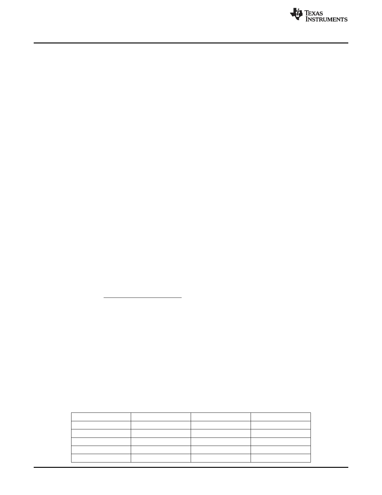
Table 17-1. Commonly Used Baud-Rate Settings for 32 MHz System Clock
Baud Rate (bps) UxBAUD.BAUD_M UxGCR.BAUD_E Error (%)
2400 59 6 0.14
4800 59 7 0.14
9600 59 8 0.14
14,400 216 8 0.03
19,200 59 9 0.14
166
USART SWRU191C–April 2009–Revised January 2012
Submit Documentation Feedback
Copyright © 2009–2012, Texas Instruments Incorporated
 Loading...


